Define the Ray Diagrams for Lenses
When drawing ray diagrams for thin lenses, we can assume that the lens is infinitely thin. Instead of considering refractions at each surface of the lens, we draw the diagram with a single sharp bend at the center of the lens.
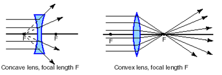
To figure out the position and size of an image seen through a thin lens, you can draw a scaled diagram of the lens showing the central optic axis with the focal point of the lens, f, marked on both sides of the lens. A convex or converging lens is one which takes all parallel incoming light and focuses it at a distance f from the lens. The focal length depends on both the index of refraction of the lens and on its shape. A concave or diverging lens takes light coming in parallel and makes it look like it is coming from the focal point behind the lens. This is indicated by giving it a negative focal length.
The following principal ray diagram is for an object at a distance greater than f from a convex or converging thin lens.
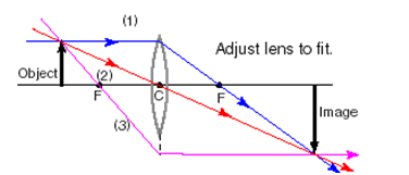
Once you draw in the object, three principal rays are easy to draw in any ray diagram:
#1: A light ray drawn from the top of the object parallel to the optic axis will refract and pass through the focal point on the far side of the lens.
#2: A light ray can be drawn from the top of the object through the center of the lens (c) and the refracted ray will continue straight along the same path.
#3: A light ray drawn from the top of the object through the focal point, f, refracts parallel to the optic axis.
The image is where these three rays intersect. In this case, the image is larger, inverted and situated past 2f. If the drawing is done carefully to scale, the exact distance and height of the image can be measured from the diagram.
The following principal ray diagram is for an object at a distance greater than f from a concave or diverging thin lens.
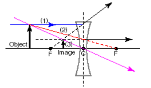
In the case of a concave thin lens, the focal length is negative and marked on either side of the lens, and the three principal rays are drawn as follows (your eye is to the right of the diagram):
#1: One ray is drawn from the top of the object to the lens, parallel to the optic axis. It is refracted along the extension of the line connecting the focal point behind the lens and the point where the incident ray hits the center line of the lens. (This extension is shown as a dotted line extending from F on the left of the diagram.)
#2: A light ray is drawn from the top of the object to the focal point past the lens, and the refraction is drawn parallel to the principal axis from the point where the incident ray intersects the center line of the lens. It is useful to extend this refracted ray behind the lens to find any virtual images.
#3: A light ray can be drawn from the top of the object through the center of the lens, which continues in a straight line.
Recall that a virtual image is an image that cannot be seen on a screen placed at this position, because the light only seems to be coming from behind the lens, but does not actually go behind the lens. In this case the virtual image is where the three extended reflected rays intersect. Here, the image is erect, smaller than the object and situated between f and the lens. If the drawing is done carefully to scale the exact distance and height of the image can be measured from the diagram.
Another method is to use the lens equation:
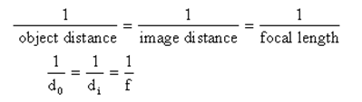
where object distance is measured from the center of the lens and is always positive, the image distance is positive for real images and negative for virtual images, and the focal length is positive for convex lenses and negative for concave lenses.
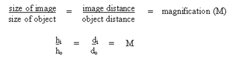
The height of the image can be calculated by using:
where the height of the object is always positive, and if the height of the image and the magnification is negative, the image is inverted. If the absolute magnitude of the magnification is greater than one, the image is larger than the object, and if the magnification is less than one, the image is smaller than the object.