Calculate the open circuit voltage, Electrical Engineering

Assignment Help:

This question is designed to give you practice in manipulating circuit equations using j notation, and to demonstrate that techniques that you have already studied in the d.c. context can be applied equally successfully to the solution of steady-state a.c. problems.

485_Calculate the open-circuit voltage.png

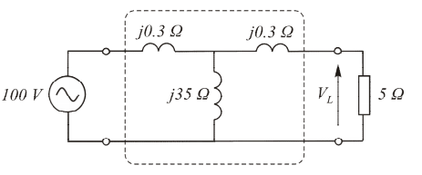
The sketch (right) shows the approximate equivalent circuit of a real transformer (inside the dotted line) with its parameters referred to the primary side, and with a referred load resistance of 5 ω. Find

(a) the open-circuit voltage VL , and

(b) the voltage across the 5 ω 'referred' load, by the following three methods.

 Method 1: Direct approach. First find the open circuit voltage by simple 'potential divider' approach (but with complex impedances Z replacing the simple resistances we used under d.c. conditions). Then find the equivalent series impedance of the two parallel branches on the right, and again use the 'potential divider' idea to find VL. The calculations are lengthy, and you will probably find it best to use polar form for the multiplications and divisions.

Method 2: Thévenin. Find the Thévenin equivalent circuit for the transformer and 100 V supply. Then apply the load and use the potential divider approach.

Method 3: Nodal Analysis. Call the node at the top of j35 node a and that at the top of the 5 ω load node b, with the reference (zero) node at the bottom. Write down the nodal equations in terms of the complex impedances, and solve for Vb.

Calculate the % change in the output voltage when the load is applied (this is known, as the 'regulation'). What would you expect the regulation to be if the transformer were ideal?


Related Discussions:- Calculate the open circuit voltage

Network analysis, what are the advantages and disadvantages of Thevenin the...

what are the advantages and disadvantages of Thevenin theorm over Norton theorem

Design a combination circuit, Design a combination circuit to combine two s...

Design a combination circuit to combine two signals as follows: v 0 = -2 v 1 - 8v 2 - v 3 The following specifications are imposed: R in ≥ 20 k? at all inputs All

Explain the working of positive clamper, Q . Explain the working of Positiv...

Q . Explain the working of Positive Clamper? Positive Clamper: The circuit for a positive clamper is shown in the figure. During the negative half cycle of the input signal,

Explain the working of a depletion type mosfet, Q. With a cross sectional v...

Q. With a cross sectional view, explain the working of a depletion type MOSFET Draw a biasing amplifier circuit DEPLETION-TYPE MOSFET: Two types of FETs: JFETs and MOSFETs. MOS

Amper circuital lw, the plot of amper circuital law by using matlap?

the plot of amper circuital law by using matlap?

Usage of fixed bias, Usage: Because of the above inherent drawbacks, f...

Usage: Because of the above inherent drawbacks, fixed bias is seldom used in linear circuits (that is those circuits which use the transistor like a current source). Instead,

Discuss the closed-loop behavior, Q. Discuss the closed-loop behavior? ...

Q. Discuss the closed-loop behavior? Consider an elementary feedback control system, as shown in Figure, with H = 1. The output variable c and the input e to the direct transmi

Applications of operational amplifiers, Q. Applications of operational ampl...

Q. Applications of operational amplifiers? An op amp along with a few external components (resistors and capacitors) is capable of performing many different operations-hence th

Survey for designing of a cross-over circuit for loudspeaker, Crossovers ar...

Crossovers are generally used with loudspeakers having multiple drivers. Loudspeakers with single drivers are unable to cover the entire frequency range i.e from low to high freque

Write Your Message!

Captcha
Free Assignment Quote

Assured A++ Grade

Get guaranteed satisfaction & time on delivery in every assignment order you paid with us! We ensure premium quality solution document along with free turntin report!

All rights reserved! Copyrights ©2019-2020 ExpertsMind IT Educational Pvt Ltd