Calculate the magnitude of maximum bending moment, Mechanical Engineering

Assignment Help:

Calculate the magnitude of maximum bending moment:

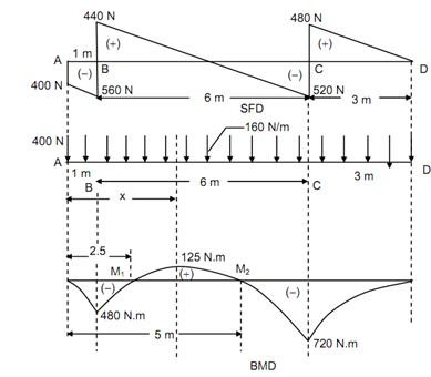
The shear force diagram for the overhanging beam is illustrated in Figure. Draw the loading diagram & bending moment diagram. Determine the magnitude of maximum bending moment & situated the point of contraflexure.

2366_Calculate the magnitude of maximum bending moment.png

Solution

Let us analyse the shear force diagram specified in Figure .

At A

The shear force diagram suddenly reduces from 0 to - 400 N. It denotes that there is a downward point load of 400 N at point A.

Between A and B

The shear force diagram is an inclined straight line and reduces from - 400 N to - 560 N. It denote that there is a consistently distributed load of (560 - 400 = 160) ⇒ 160 × 1 = 160 kN/m among A and B.

At B

There is a sudden enhances from - 560 N to + 440 N at B. It denotes that there is a support reaction of 1000 N at B.

Between B and C

As the shear force diagram varies linearly from + 440 N to - 520 N among B & C. It denote that a u.d.l. of (440 + 520 = 960) 960 /6= 160 kN/m is acting between B and C.

At C

At C, the shear force diagram enhance suddenly from - 520 kN to 480 N. It denote that there is a support reaction of 1000 N (520 + 480) at C.

Between C and D

The shear force diagram is an inclined straight line which denote that there is a uniform ally distributed load of 480/3 = 160 kN/m from C to D.

Bending Moment

BM at A and D, MA = MD = 0.

 BM at B, M B =- (400 × 1) - (160 × 1 × (½) ) =- 480 N m

BM at C, M C = - (160 × 3 × (3/2)) =- 720 N m

Maximum Bending Moment

SF at any section XX among B and C,

Fx = +1000 - 400 - 160x

For maximum bending moment, Fx must be equal to zero.

600 - 160x = 0

∴          x = 3.75 m

∴ M max            = (1000 × 2.75) - (400 × 3.75) - (160 × 3.75 × (3.75/2)

                            = + 125 N m

Maximum positive bending moment take places at a distance of 3.75 m from the end A, where SF changes sign.

Maximum negative bending moment takes place at a support C where SF changes sign.

∴          Mmax (negative) = - 720 N m

Points of Contraflexure

Let M1 and M2 be the points of contraflexure, where BM is zero. However at any section XX among B and C at a distance x from the end A.

M x   = 1000 ( x - 1) - 400x - (160 × x × (x/2) )

or         1000x - 1000 - 400x - 80x2 = 0

80x2 - 600x + 1000 = 0

8x2 - 60x + 100 = 0

2x2 - 15x + 25 = 0

(2x - 5) (x - 5) = 0

Therefore,        x = 2.5 m  and   5 m.


Related Discussions:- Calculate the magnitude of maximum bending moment

Types of electron beam welding gun, TYPES OF ELECTRON BEAM WELDING GUN ...

TYPES OF ELECTRON BEAM WELDING GUN   Diode (Cathode - anode) Gun : In this gun, the beam shaping electrode and the emitter are both at the same electrical potentials. These

Mockup test, we perform mockup test to 10 tube with tubesheet. please give ...

we perform mockup test to 10 tube with tubesheet. please give the cutting plan?

Determine the joint rotations, The rigidly jointed frame shown in Figure ha...

The rigidly jointed frame shown in Figure has bending stiffnesses such that EI AB = 1000kNm 2 and EI BC = EICD = 1600kNm 2 . (i) Determine the joint rotations at B and C.

Thermal stress, how did the formula derived smax = Ed1 a ?T/d 2

how did the formula derived smax = Ed1 a ?T/d 2

Wire melting characteristics, WIRE MELTING CHARACTERISTICS A non linear r...

WIRE MELTING CHARACTERISTICS A non linear relationship exists between the rate at which the wire is fed into the arc and the current required to burn it off to maintain a constan

Flange facing and surface finish, Q. Flange Facing and Surface Finish? ...

Q. Flange Facing and Surface Finish? Raised face flange facings are preferred. Flat face flanges to be used only when mating with like equipment (fabricated from brittle mat

How is rending stress designed in plain concrete footing, How is rending st...

How is rending stress designed in plain concrete footing? Rending Stresses Also design the plain concrete footing based on bending moment and shear considerations. In wall f

Net positive suction head, A pump station has been designed to lift water o...

A pump station has been designed to lift water out of a 6 metre deep pit (vented to atmosphere) via a centrifugal pump mounted at ground level. Liquid conditions

Computer aided manufacturing, Computer systems to plan manage, and control...

Computer systems to plan manage, and control the operations of a manufacturing plant through either direct or indirect computer interface with the plants production resource

Cad, c programms fpr cycloidal motion

c programms fpr cycloidal motion

Write Your Message!

Captcha
Free Assignment Quote

Assured A++ Grade

Get guaranteed satisfaction & time on delivery in every assignment order you paid with us! We ensure premium quality solution document along with free turntin report!

All rights reserved! Copyrights ©2019-2020 ExpertsMind IT Educational Pvt Ltd