Bay cooling in Aircraft:
There are two methods of bay cooling, they are:
• Ram air cooling
• Fan air cooling
RAM AIR COOLING
For ram air cooling, the aircraft has to be moving forward at sufficient speed to enable the cooling air to be picked up by the air scoops in the external skin. This cold air is ducted into the APU bay and passed onto various hot zones to provide a cooling medium. The air is then vented overboard through exhaust ducts.
FAN AIR COOLING
Cooling fans are fitted to the APU gearbox to provide a supply of cooling air to the APU when it is running. The cooling air is pumped into the APU compartment and then vented overboard. The air from the fan is also used to cool the generator drive oil and the exhaust duct on some APU installations.
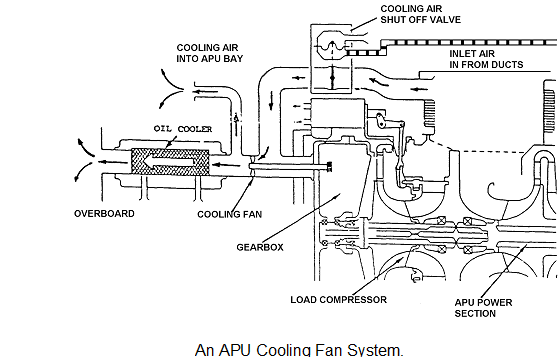
The main components are the:-
• cooling air fan.
• cooling air shut-off valve.
Air is drawn from the normal intake plenum or an external intake and is directed along the cooling air ducts to the cooling fan shut-off valve (when fitted). The shut-off valve closes on APU shutdown to prevent air from entering the compartment to support combustion in the event of an APU fire.
The cooling fan is linked to the APU gearbox and as long as the APU is running, the fan is turning. Air is also used to cool the oil within the APU lubricating system (on some APU's), however, such air is usually ducted overboard and not into the APU compartment. Upstream of the oil cooler the cooling air is ducted into the APU bay an/or the exhaust insulating ducting to provide general cooling.
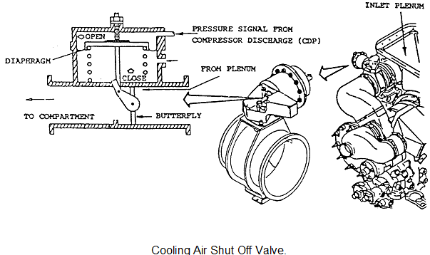
Cooling Fan Shut-Off Valve
The cooling valve figure 18.33. is a spring-loaded closed butterfly valve with a pneumatic actuator. When the APU is started, the compressor discharge pressure is ported to the top of the diaphragm. The piston moves down with increasing air pressure and opens the valve against the spring pressure. The cooling air then flows to the compartment. On APU shutdown the air pressure is reduced and spring pressure closes the valve.
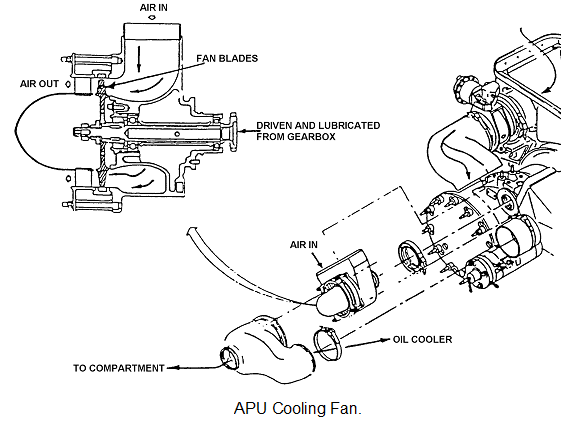
Cooling Fan Arrangement
The cooling fan is attached to the APU gearbox, (figure 18.34) and is designed to run at extremely high speeds, the fan boosts the air from the intake plenum (or ambient) into the APU compartment or the coolers etc.
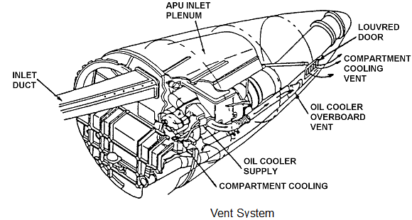
Overboard Venting
Figure represents a typical APU bay overboard vent arrangement. The cooling air is directed into the compartment and also to the oil cooler, this air is then vented overboard along a separate duct. Compartment cooling air is vented overboard, through a louvered door at the rear of the compartment.