AUTOMATIC SYNCHRONISING:
Automatic Synchronisation uses engine driven synchronising alternators to detect electrically any increase or decrease in a slave engine's speed. Each alternator's output voltage is directly proportional to its engine speed and this voltage is sent to the corrector motor on the slave engine to modify its RPM if a difference in output exists by comparison with the master engine.
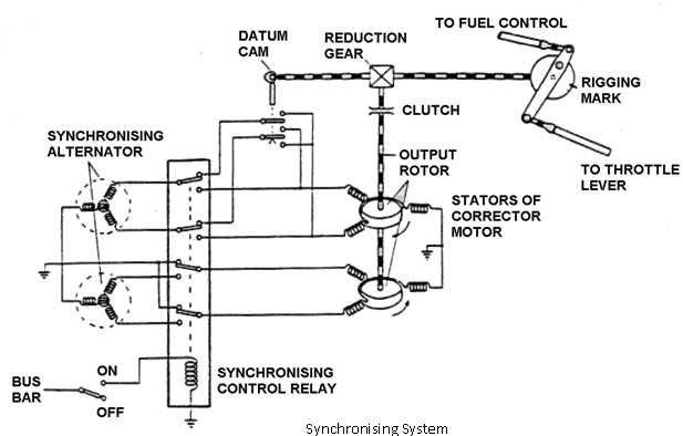
The corrector motor assembly consists of two stators mounted on a common rotor. One stator is fed from the master engine alternator and the other stator is fed from the slaw alternator. The wiring from the alternators is in such a way that the magnetic fields produced in the stators are in opposition. The output from the common shaft is through a clutch assembly and reduction gear to the slave engine throttle controls.
Rotation of the shaft imparts a small linear movement to the control lever and operates the input rods to the fuel and propeller control units. The operation of the PCU will, depending on the direction of correction, increase or decrease the blade pitch which with the fuel control unit will cause the slave engine's RPM to rise or fall until it equals the speed of the master engine.
The range of the synchronising system is restricted, so that a master engine failure, or for that matter an overspeed, only affects the slave engine to a limited extent. On the output shaft is a datum cam which causes the corrector motor to return to the mid point of the operating range when the system is switch off.
The opposition windings of the stators in the correction motor are wired so that the slave motor will influence the rotor in the decrease RPM direction and the master stator will influence it in the increase RPM direction.
A further method of propeller synchronising is the use of magnetic pick ups and stepper motor.
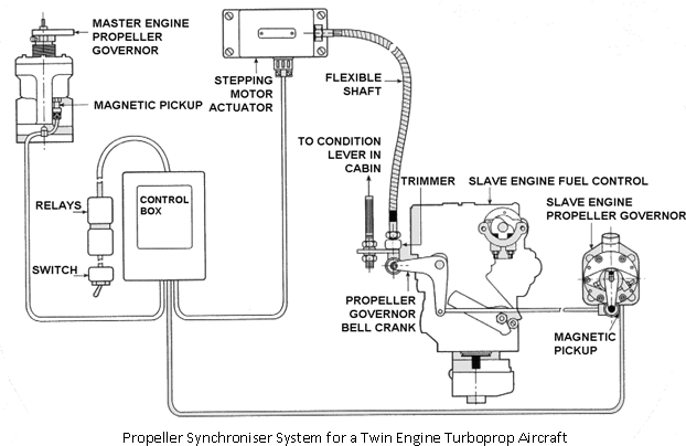
One engine is designated as the 'Master Engine'. When the RPM of this engine is adjusted by the pilot and the synchroniser system is on, the RPM of the slave engine will automatically adjust to the same RPM.
Each propeller governor contains a rotating magnet and a magnetic pickup which produces alternating current as the governor rotates. The frequency of this AC is proportional to the speed of the governor. The outputs from the two governors are compared in the synchroniser control box, and an output signal is sent to the DC stepping motor actuator. A flexible steel shaft connects the actuator to the propeller governor bell crank on the fuel control of the slave engine. If the slave engine is slower than the master engine, the control box will drive the actuator motor in a direction that will move the bell crank and connection arm on the slave motor fuel control and the propeller governor, in the correct direction to increase its RPM.
The operation of the synchroniser system is simple. It is left off during takeoff and landing. When the aircraft is trimmed for cruise flight, the condition levers of the engines are manually adjusted to bring their RPM close enough to the same speed that the engines will be within the synchronising range. Then the synchroniser is turned on. Any difference in RPM is sensed, and the slave engine fuel control and propeller governor are adjusted so the slave engine RPM matches that of the master engine.
When making power changes in flight, adjust both condition levers together to keep the RPM within synchronising range. If the engines get out of synchronisation beyond the limits of the system, the actuator will be driven to the limit of its travel. Turn the system off and the actuator will return to its centre position. Manually synchronise the engines and turn the system on. It will fine tune the synchronisation and hole the engines together.