The single phase alternator
The underlined italicised terms in the following text identifies terms that you should understand and remember. The simple two pole generator described previously has a coil wound on a rotor that rotates in a stationary magnetic field produced either by a permanent magnet (used in low power machines only) or by a field coil . The output voltage induced in the rotor is connected to the output load by carbon brushes bearing on a commutator that reverses the output every half cycle to convert what would otherwise be an ac output into a pulsating (full wave rectified) DC output.
The alternator uses slip rings instead of a commutator which reduces complexity of construction and the risk of sparking, improving long term reliability. The slip rings make continuous connection to the output producing an AC output that may be rectified with a diode pack to produce DC if required.In practice, given that the output of an alternator will be ac, it is usually better to change the rotor/stator windings arrangement so that the field coils are wound on the rotor and the induced output voltages are induced in stator coils wound on the stator .
The reasons for this are:
1) only one pair of slip rings are required (to energise the rotating field coil) regardless of the number of phases produced by the alternator (three phases is common).
2) The rotating coil can be supplied from a low voltage DC source and it is better to use slip rings for this purpose than to output the often high induced output voltage.
3) Insulation of the output coils is easier to achieve if the coils in which the output voltage is generated are stationary rather than rotating.
4) If permanent magnets can be used on the rotor (this is only suitable for low power generators due to difficulty and expense of manufacturing specially shaped and strong permanent magnets of a suitable size), then no electrical connection is required to the rotor and therefore no slip rings are needed at all. This is a major advantage for reliability.
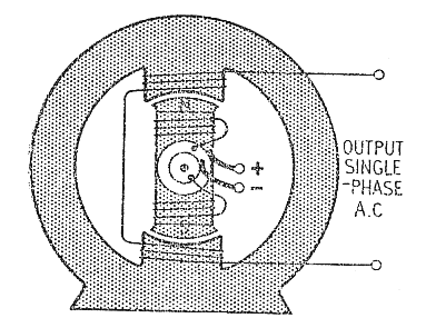
A simple single-phase alternator is shown in the figure below. The rotor is supplied by a low voltage DC supply via slip rings to produce a NS pole pair on the rotor. As the rotor turns, the changing magnetic field induces a single phase AC output voltage in the stator coils. These are connected in series with the number of turns on the coils selected to produce the required output voltage when turning at the rated rotational speed of the alternator and the designed DC rotor current.
A complete cycle of ac is produced each revolution of the rotor, so the frequency of the output voltage in Hz is equal to the rotor speed in revs/second. This can be a problem if a stable output frequency is required even though the speed of the rotor may change. E.g. aircraft engines drive alternators that produce ac supplies to the instruments. Typically this needs to be held stable at 400Hz even though the engine speed may change. (400Hz has been chosen because a high frequency allows smaller (and therefore lighter) transformers etc and yet low enough to avoid losses due to eddy current losses in the magnetic materials, giving acceptable efficiency). This problem used to be solved by ingenious constant speed mechanical gearboxes between the engines and the alternators that maintained a constant output shaft speed despite changes of the input shaft speed. This is a complex and
expensive solution to the problem and adds weight. More recently, the development of reliable high power electronics has become available that makes it preferable to electronically rectify the ac output of the alternator to produce a DC voltage that is then electronically converted back to AC at
the required stable frequency using ‘inverters’. This ensures that the frequency is always stable at 400Hz , independent of engine speed.
If several pairs of magnetic poles are wound on the rotor (note every N pole must have a corresponding S pole, so they always occur in pairs), then several cycles of AC will be induced in the stator coils for every revolution of the rotor, one cycle for every N-S-N transit of the rotor poles past the relevant stator coil. If the rotor has p pairs of magnetic poles, then p cycles of AC will be induced by each revolution of the rotor. The diagram below shows a single-phase alternator that produces an ac voltage with frequency four times the rotational speed (it has 4 pole pairs).
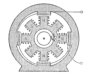
The output is single phase because the field coils are located in the same position relative to the poles on the rotor. (i.e. each field coil has, say, a N pole passing it at the same time). The stator coils are all connected in series to produce the output voltage. An important problem with the single phase alternator is that when a current is delivered to a load, a torque reaction occurs between the rotor and the stator that must be overcome by the primary drive.
The torque reaction occurs because there will be a current flowing in the stator coils as power (P=I.V) is delivered to the load. This current reacts against the magnetic field of the rotor to produce a motor effect that acts to try to oppose the rotation of the rotor. The torque produced pulsates sinusoidally with a frequency of pωt and causes vibration, material fatigue and noise.
This does not happen if the stator coils are arranged to produce a three-phase output (see below). The torque reaction produced by each of the three phases of the stator windings add up to produce a constant torque reaction.