What is the role of capacitors in the ac analysis

Assignment Help Electrical Engineering
Reference no: EM131393712

AC Models

Introduction:

Lab is based on the AC models of a transistors. After the transistor has been biased with a Q-point near the middle of the load line, we can couple a small AC voltage into the base. This creates an AC collector voltage which is larger than the base voltage and hence this arrangement results in an amplifier with a voltage gain.

Please review the following videos before getting started with this lab:

1. Watch the video: "Video 3: Fundamentals of breadboard"

2. Watch the video: "Video 4: Basic electrical components"

3. Watch the video: "Video 5: Simple resistive circuit with NI myDAQ"

Materials and Equipment:

Hardware Parts (In the Toolbox):

  • An NPN transistor: 2N3904
  • Five resistors: Two - 1kΩ, 2kΩ, 10kΩ and 40kΩ
  • Three Capacitors: 1μF, 100μF
  • Jumper wires

Equipment:

Software equipment:

  • Multisim
  • Virtual Instruments (in Multisim)
  • Agilent Multimeter

Hardware Equipment:

  • Breadboard
  • NI myDAQ Instrument device
  • Screw Driver
  • Screw Terminal connector
  • USB Cable
  • Multimeter with probes
  • Function Generator, Oscilloscope, Multimeter from NI ELVISmx Intrument Launcher

Procedure:

This lab has to be implemented in hardware (using NI myDAQ) as well as Software (Multisim)

Part A:

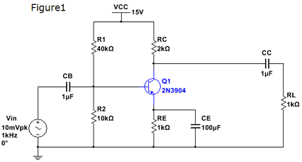
1. Analyze the circuit or the amplifier shown in Figure 1. Determine the voltages VB, VE, VC, VBE and VCE. Using the beta value of 100, determine the gain of the amplifier (AV). (Include 20% tolerances for resistors and capacitors).

2. Construct the circuit shown in Figure 1 on the breadboard using the hardware parts.

3. Using the jumper wires, screw driver and screw terminal connector, connect the board to NI MyDAQ Instrument Device.

4. Using the function generator in NI ELVISmx Instrument Launcher, provide the voltage (Vin). Use channel AO0 pin on the NI myDAQ Instrument Device to provide this voltage. Make sure the frequency is 1 KHz frequency.

5. Using +15V pin out on the Instrument Device provide the supply voltage VCC.

6. Perform the DC Analysis by disconnecting the capacitors and measuring VB, VE, VC, IB, IE and IC.

7. Place the capacitors back and using pin AI0 on the NI myDAQ Instrument Device, measure the required voltages: VB, VE, VC VBE, VCE.

8. Measure the currents: IC and IE using the Multimeter.

9. Use AI1 on the NI myDAQ Instrument Device to measure the load voltage VRL. Record the measurements and compare them with the calculated values in step 1.

10. Using the input voltage Vin, base voltage VB and load voltage VRL, determine the gain of the amplifier (AV).

1265_Figure.png

Part B:

1. Download the "Lab troubleshooting" file and perform analysis for the circuits to locate the fault embedded in the circuit.

2. Step by step measure the key point's value with Agilent multimeter. Carefully analyze each measured value to locate the fault within the circuits. Fix the fault and with the corrected fault in the newly circuit, measure and record the new values.

Review questions:

1. Compare a calculated and measured values. Discuss whether the values are the same of different. If they are different, provide the reasoning.

2. Does the DC analysis confirm your calculations?

3. What is the gain of the amplifier? Does the gain obtained from analysis match the measured gain? If not, what is the problem and how would you fix it?

4. What is the role of capacitors in the AC analysis?

5. Did you find any clipping of the collector current? If so, how did you adjust the circuit to avoid clipping?

Deliverables:

1. DC and AC analysis of the circuit and all the calculations including gain of the amplifier from step 1.

2. Place your student ID card on the breadboard and take a picture of the circuit board and pin out on the NI myDAQ Instrument Device.

3. Take screenshots of the measurements obtained from function generator and Oscilloscope and Multimeter on the NI ELVISmx Instrument Launcher on your screen.

4. Screenshots of the measurements from DC analysis (without the capacitors). Screenshots of the measurements from AC analysis (with the capacitors). Screenshots of the input voltage Vin, base voltage VB and load voltage VRL.

5. Screenshots of collector voltage (Vc) (if any clipping).

6. Tabulate the data from analysis and measurements to confirm the gain of the amplifier.

Attachment:- Lab Assignment.rar

Reference no: EM131393712

Questions Cloud

Monopolist produce in order to maximize profits : A monopolist faces market demand given by P = 100 – 3Q. For this market, MR = 100 – 6Q and MC = 25. What quantity of output will the monopolist produce in order to maximize profits?
What features of disney films support or undermine cronon : Defend your claims by citing specific passages in Cronon and specific details from movies. Do you agree with Lutts that films like Bambi cultivate in us a problematic view of nature? If so, what is that view? If not, how can we harmonize those vi..
Design a personalized key holder for a recreation vehicle : Design a personalized key holder for a recreation vehicle that is used occasionally. When not in use, it must hang on a wall or key rack. The material is to be lightweight and colorful.
Create an ethics code for a hypothetical government entity : Your assignment is to create an ethics code for a hypothetical government entity or agency. Please describe the agency you propose, then create an ethics code for your agency. You can find helpful suggestions at the Institute for Local Government...
What is the role of capacitors in the ac analysis : Compare a calculated and measured values. Discuss whether the values are the same of different. If they are different, provide the reasoning. What is the role of capacitors in the AC analysis
Show the microphone in phantom lines : A 020-mm tapered hole (large end) with a 3-mm-wide slot on top is required for attaching the microphone to the holder. Lay out the holder and show the microphone in phantom lines.
Are citizens more likely to provoke inappropriate uses : For this assignment you need to submit your research methods section of your paper. You will need to explain how your study was carried out. What research design and methodology did you use? Your explanation needs to be clear enough that it would..
Certificate of deposit matures : Suppose your $50,000 certificate of deposit (CD) matures and you transfer the funds to your checking account. Suppose that the inflation rate has been 3 percent per year for several years, and the unemployment rate has been stable at 5 percent. Unant..
Design a noninverting amplifier : Lay out the design of the plate and include on the drawing the production and specification data that you would submit with your design.

Reviews

len1393712

2/14/2017 1:26:37 AM

I need help on this lab assignment. Place your student ID card on the breadboard and take a picture of the circuit board and pin out on the NI myDAQ Instrument Device. Screenshots of the measurements from DC analysis (without the capacitors). Screenshots of the measurements from AC analysis (with the capacitors). Screenshots of the input voltage Vin, base voltage VB and load voltage VRL.

Write a Review

Electrical Engineering Questions & Answers

  How much time will it take to rotate the part 180°

How much time will it take to rotate the part 180°?

  Problem regarding the filter design

You are to design a continuous-time, second-order, lowpass filter that has the following specifications.

  Find the speed of the proton at a certain location

At a certain location, the horizontal component of the earth's magnetic field is 3.70 10-5 T, due north. A proton moves eastward with just the right speed for the magnetic force on it to balance its weight. Find the speed of the proton.

  Consider the nmos circuit in figure

Consider the NMOS circuit in Figure. - Determine vO when vX = vY = 2.9 V. -  What are the values of vGSX , vGSY , vDSX , and vDSY?

  Design by direct implementation the electronic circuits

Design by direct implementation the electronic circuits for equations as the following logic equations using any real 1, 2, or 3 input logic gates. Assume all signals are high true (positive logic) and do not simplify the equations.

  Impact of electron energy

Briefly discuss the impact of electron energy, electron current and target on the Bremsstrahlung generated.

  What is the minimum spacing of the tones

What is the minimum spacing of the ‘‘tones'' in order to maintain them coherently orthogonal?

  Determine apparent power for a parallel rc circuit

A parallel RC circuit is connected to a 100-volt 60 Hz source. The current flow through the resistor is measured and found to be 10amps. The current flow through the capacitor is measured and foundto be 10 amps.

  Determine the maximum and minimum inductor currents

A flyback converter is to be designed to provide 10V at 18A from a smooth 200V source. Isolation between the input and output is required. The switching frequency is 200kHz and the duty cycle is 0.4.

  Find transition point for p channel and n channel transistor

Find the transition points for the p-channel and n-channel transistors. -  Sketch the voltage transfer characteristics including the appropriate voltage values at the transition points.

  Determine required sampling rate and line speed

Consider a PCM-TDM system in which 24 signals are to be processed. Each signal has a baseband bandwidth of 3 KHz. The sampling rate has to be 33.3% higher than the theoretical minimum, and 8 bits are to be used.

  By what percentage can the energy consumption be reduced

Suppose that the cost of electrical energy is $0.12 per kilowatt hour and that your electric bill for 30 days is $60 (power usage only, not including other charges or taxes) Assume that the power delivered is constant over the entire 30 days.

Free Assignment Quote

Assured A++ Grade

Get guaranteed satisfaction & time on delivery in every assignment order you paid with us! We ensure premium quality solution document along with free turntin report!

All rights reserved! Copyrights ©2019-2020 ExpertsMind IT Educational Pvt Ltd