Reference no: EM131160236
Objectives
1. To examine the operation of the PAM modulator with natural and flat sampling
2. To examine the operation of the sample and sample & hold circuits
3. To examine the waveforms of the signals and the relation between the sampling pulses and the PAM signals
Instruments
• MCM30/EV Module
• Oscilloscope
Theory
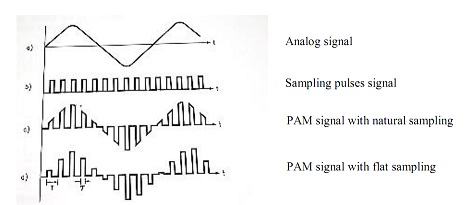
A PAM signal is a sampled signal consisting in set pulses which amplitude is proportional to the amplitude of the analog signal.
The sampling can be natural or flat one. For natural sampling, the sampled signal follows the shape of the analog signal while flat sampling, the amplitude of the sampled signal pulses reproduces the amplitude taken by the analog signal in the sampling instant.
Procedure
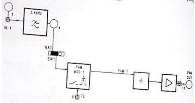
Natural sampling
The block diagram of the PAM modulator with natural sampling is as shown below
• Power the module
• Set the circuit to PAM-1 channel mode and set SW 1= Nat, SW2=1CH, SW3=2
• Connect 1 kHz-2Vpp to the analog input of the PAM modulator (connect TP24 to TP1 and adjust the 2Vpp signal level)
• Connect the oscilloscope to the analog input signal (TP 1) and to the output of the PAM modulator (TP1 1)
Exercise
i. What can you say about the PAM signal?
ii. Where are the sampling pulses measured for the PAM-1 modulator? How much is the pulse frequency, the period and duration?
iii. Change the sampling pulse width (set SW3 = 1) and note the corresponding PAM signal Variation.
Flat sampling
The block diagram of the PAM modulator with flat sampling is as shown below
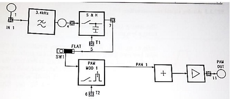
• Set the circuit to PAM-1 channel mode and set SW1=flat, SW2=1CH, SW3=2
• Connect 1kHZ-2Vpp to the input IN1 of the PAM modulator (connect TP24 to TP1 and adjust the 2Vpp signal level)
• Examine the waveforms of the analog input signal (TP1), of the signal at the Sample and Hold output (TP7), of the sampling pulses for the S&H (TP5)
• Note that the signal is sampled at the beginning of the sampling pulse, and the amplitude is kept constant up to the next pulse. Across TP 7, there is step signal which approximates the analog input signal.
• Examine the waveforms of the sampling pulses for the modulator (TP6) and the output PAM signal (TP 11), and note that the step signal is sampled when the level is stable
• See that the PAM pulse have constant amplitude for all their duration
• Change the sampling pulses width (set SW3=1) and note the corresponding variation of the PAM signal
Exercise
i. The PAM signal is missing across TP11. Explain
ii. Sketch the waveform at TP5, TP6, TP7, TP 11
iii. Compare the level of distortion of the reconstructed signal with natural and flat sampling.
State where each sampling is suitable.