Reference no: EM131229924
55 - 7947 Equipment Engineering and Design Assignment
Part A - Vibration problem
Excessive vibration in a fan
Centrifugal fan on foundation used to force heated air over drying malt Specification:
- 2.5 m dia impeller
- spherical roller bearings
- multiple v-belt drive
Operation problems:
- Pulsations, on closure of inlet vanes (flow control device)
- Excessive vibration levels in spite of careful impeller balancing.
- Prominent second and third harmonics in the frequency spectrum
- When run down, irregular knocking noises produced.
Also damage to machine identified on inspection:
- Failure of two 24mm bolts holding steel pedestal to concrete foundation block
- Partial disintegration of grouting between pedestal & foundation
- Some damage to shaft surfaces where bearings attached.
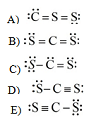
Using accelerometers, vibration amplitude was measured at various heights down the pedestal and foundation:
Questions -
1. What are the likely causes of the vibration problems?
2. What would you, as plant engineer, recommend to prevent recurrence?
Part B - Hydraulic Problem
Background
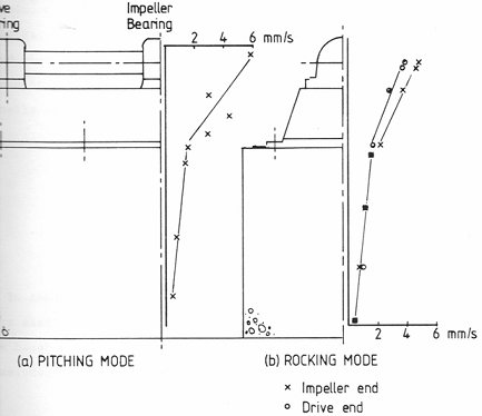
You are the factory engineer working in a highly automated modern earthmoving equipment factory that has been in operation for some years. You are in charge of the equipment described below. The circuit shows a hydraulic system. The hydraulic cylinder (item 10) is one of several fully automatic clamping stations that hold large pieces of steel together while they are welded together.
The cylinder operates and holds a nominal pressure of 200 bars for approximately 15 minutes, then is off for approximately 2 minutes while the welded component is removed and re charged with un-welded components. The relief valve (item 5) is set to 230 bars. Materials for the production process are rigorously checked and are very consistent.
When pressure is required for the welding process, the Programmable Logic controller (PLC) energises the 2 position, 2 port spring return solenoid valve (item 6).
When the correct clamping pressure has been achieved, the pressure switch detects system pressure as being correct and the resulting signal is used by the PLC to signal valve 6 via its solenoid to unload the pump. An accumulator is fitted to accommodate any equipment internal leakage.
During the welding process; if the pressure switch (item 11) sees a drop in pressure bellow the pressure switch differential setting; valve 6 is re-energised, until correct clamping pressure is regained.
The machine is capable of operating continuously as production requirements demand. The Hydraulic power-pack is outside the main machine guard, can be adjusted and visually inspected safely while the machine operates and is away from the welding process. In general the plant is so well automated personnel may manage a number of different machines at any time.
A fixed speed AC motor is used to power the system.
|
Item
|
Description
|
|
1
|
Strainer (In tank Suction)
|
|
2
|
Fixed displacement gear pump approx. 5 lt/ min
|
|
3
|
Fixed speed Motor (AC)
|
|
4
|
Pressure filter with bypass (opens at 2bar)
|
|
5
|
2 stage Pressure Relief Valve cracks at 230 bar
|
|
6
|
2 Position Directional Control valve
|
|
7
|
Non Return Valve
|
|
8
|
Accumulator:- Nitrogen filled bag type
|
|
9
|
3 Position Directional Control Valve
|
|
10
|
Hydraulic Cylinder
|
|
11
|
Pressure switch activated 200 bar, differential 10 bar
|
The problem
When you arrive in the morning the oil reservoir is so hot you cannot hold your hand on it, this is not the normal state. The tank is usually at ambient temperature.
The oil level appears to be correct and the oil looks clean and there appears outwardly to be no problems.
The system seems to be losing its capability to achieve its welding pressure.
What are the possible causes of the problems; this may include technical and human issues.
Suggest any improvements to the circuit that might protect against this occurrence in the future? You are not expected to suggest major hydraulic changes as the circuit is a standard circuit that works well.
As an aside what maintenance strategy could be applicable to this piece of equipment and why? A list of detailed maintenance activities would be inappropriate and could lose marks.
Full explanations are required as to how you arrive at your conclusion, with any theory being applied to the problem at hand. You must tell me how the issues/faults you identify have resulted in the symptoms being experienced. Please be brief, succinct and to the point. I see this as a technical report.
Use your experiences gained in labs, seminars as well as reading will be required to inform your answer.
All Theory and discussions must be directed and related to this problem. Lists of general/generic ideas, issues, theories etc. are not acceptable and will lose marks; all discussions must be related to the problem at hand.
You must use the correct terminology, such as relieving, unloading etc. and when referring to equipment in the case study, ensure the correct name are identification numbers are always used.
Part C - Structural Failure Problem
Background
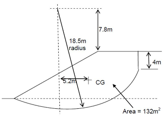
A 6 ton pressure vessel - see dimensioned drawing - was being lowered onto a "stillage" or temporary supporting structure for testing outside a factory in the open yard.. The lower lugs were attached to the stillage and as the slings were being loosened by the crane operator, the vessel tilted slightly.
At this point one of the legs of the stillage collapsed. Luckily the slings had not been removed, so the vessel did not fall - but a serious accident was only narrowly averted.
It was subsequently noticed that the ground on which the vessel and stillage were being placed sloped at 5 degrees.
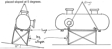
1. Why did the leg collapse? What effects or details did the designer ignore?
2. Redesign the stillage to avoid similar incidents in future, without increasing its footprint (width, length) since space is needed around it for testing.
3. Make recommendations on safe lifting and mechanical handling of the vessel.
Tips: work out the weight and the centre of gravity of the vessel. Check the load on each leg. Estimate the collapse load using a suitable formula and relevant assumptions.
Also look up the rules for similar mechanical handling procedures.
All Theory and discussions must be directed and related to this problem. Lists of general/generic design issues, management techniques etc are not acceptable and will lose marks; all discussions must be related to the problem at hand.
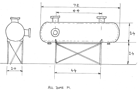
Vessel details-
Wall thickness 12mm. Hemispherical ends. Carbon steel.
Overall length 7.2m, diameter 2.4m
3 Nozzles (all on vessel centre line), pipe o/d 500mm, i/d 420mm, 500mm long.
Nozzle flanges, o/d 600mm, i/d 420mm, thickness 22mm
Stillage details
Section: 50 x 50 x 5 mm rolled steel angle. Welded construction. S275 steel (i.e. yield stress of 275 MPa).
Section Properties:
overall width 2m, length 4.4m, height 2.4m
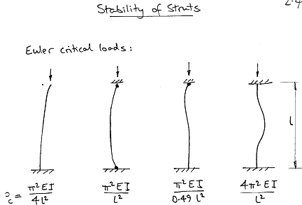
Reminder of the Euler critical loads Pc which are valid for slenderness ratio l/k > 80. What are the actual end conditions here?
Part D - Factory Maintenance problem
Problem background
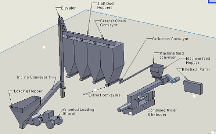
Part of a factory that manufactures extruded building products is shown below.
Dust that is processed in another factory is loaded by a wheeled shovel into a hopper and is raised via an inclined conveyor and bucket elevator to the top of the system. The dust is then distributed to storage hoppers by a large scraper chain conveyor.
Each hopper is equipped with an extract conveyor which load dust onto a collection conveyor & then onto the machine feed conveyor.
The machine hopper acts as a surge hopper, allowing an even controllable feed of dust to be added to the mixer of the main extrusion machine. Much ancillary equipment has been excluded for clarity.
The large making machine consists of a single shaft mixer where water and dust are combined and then fed through a de-airing chamber into the extruder. None of the forming or handling equipment is shown.
Product from the extrusion machine is loaded onto refractory lined bogies and processed through a dryer and kiln, which is a continuous process. If the firing process is slowed or stopped, large scrap rates and a kiln fall could follow.
The main extrusion process has to run 16 hours per day but this can fluctuate with demand. Because this is only part of a larger factory, if staffs are not working on this system, they are employed elsewhere. Two fitters and an electrician are always on duty within the factory as a whole.
The Task
The immediate task is to suggest a maintenance strategy for the equipment. The strategy should contribute to a factory wide Reliability Centred Maintenance strategy. This includes mobile and electrical equipment. Full explanations must be given and related to this equipment.
Please note any suitable condition monitoring techniques that may be appropriate, which pieces of equipment they relate to and why.
FMEA would not be appropriate as it is not expected students have a full understanding of the equipment. Suggest and justify any modifications which would increase reliability of the plant. This may include changes to layout or maintenance policies.
It is essential that any answers are very specific to this problem. Descriptions of general / generic design issues, management techniques etc. are not acceptable and will lose marks; all discussions must be related to the problem and describe how the proposed changes would improve the current solution.
|
Plant Name
|
Description
|
Function
|
Complexity
|
Maintenance difficulty
|
|
Large
wheeled loading shovel
|
Bucket loader
|
Loads processed dust into the system
|
High
|
V Easy
|
|
Incline conveyor
|
Belt conveyor with
toughing idlers. Driven by shaft mounted gear box
|
Raises dust from below ground hopper
|
Low
|
V Easy
|
|
Bucket elevator
|
Rotating belt with pressed steel buckets. Driven by shaft mounted gear box
|
Raises dust to
top of hoppers
|
Low
|
Reasonable
|
|
Scraper chain conveyor
|
300rnm centre roller chain conveyor with scrapers attached to chain by K brackets. Driven by a Large worm and wheel gearbox, direct coupled
|
Drags dust to each hopper. Gate valves can isolate hopper from scraper chain.
|
Low to Medium
|
Difficult, on top of hoppers.
Poor
accessibility to large drive
|
|
Dust hoppers
|
Hopper
|
Stores dust (100 Tin each) Only ever requires cleaning internally
|
V Low
|
N/A..
|
|
Extract conveyor
|
Belt conveyor with toughing idlers. Driven by shaft mounted gear box
|
Removes dust from hopper
|
Low
|
Easy..
|
|
Collection conveyor & Machine feed conveyor
|
Belt conveyor with toughing idlers driven by shaft mounted gearbox
|
|
Low
|
Easy..
|
|
Machine feed hopper & conveyor
|
Hopper. reduces surges. giving even feed to the machine (1 tonne capacity)
|
Has simple extract
conveyor to feed mixer
|
Low
|
V Easy..
|
|
Making machine mixer
|
Single shaft mixer with high chrome steel blades
|
Mix dust water and lime
|
V High
|
V Difficult..
|
|
Making machine extruder
|
High chrome warms and liners
|
Extrude
product.
|
V High
|
VV Difficult..
|
Check List
This is a report, so only a short introduction is required.
Do not restate the problem. Do not pad your report out with words that do not answer the specific requirements of the case study.
Word count must be shown on cover sheet and is absolute.
Do not explain what PM, CBM and breakdown maintenance is. It will be assumed that they are terms known to all readers of the report.
Do not describe specific maintenance tasks, although appropriate CM tasks would be appropriate. Remember this is about strategy.
Do not attempt to do a Failure mode analysis; you do not have sufficient information. Do not try to add costs and hourly rates; you do not have sufficient information.
The term management, in this context relates to RMC. (Process management, spares inventory, information, some redesign at a system level etc.)
Please use maintenance books, not web or book sources on conveyor maintenance. This is about maintenance strategy, the mix of different maintenance types and the justification.
Work without discussion/justification is not acceptable.
Please check your work, unintelligible grammar and English will not be accepted. Occasional typos and small errors are not a problem.
Part E - Assignment
You are the energy manager of Beatson Clark, a glass recycling and manufacturing company which collects used glass, melts it in its furnace and casts it into new forms. The furnace is fired by natural gas purchased from the national grid. The company is considering installing an Organic Rankine Cycle (ORC)to capture waste heat in the flue gases and use it to produce electrical power. The power can be exported to the grid for a profit.
You have contacted a potential supplier, Turboden Ltd.,which installs and maintains ORC equipment.
The technical appraisal of the ORC (provided by the supplier) forecasts a £182,000increase in annual profits due to this proposed installation. The ORC has a guaranteed life of four years. Using the data provided, answer the questions that follow.
- Capital cost of the ORC unit and auxiliaries = £ 518,790
- ERDF grant (payable in year 1) = 10% of initial capital
- Corporation tax on profit = 20%
- Discount rate after Tax = 13.3%
- Scrap value at the end of year 4 = £ 60,000
- Tax on profits is payable from years 2 to 5 inclusive (i.e. one year in arrears).
Your task is to independently analyse the data provided by the supplier and produce a poster (Size A1) for the management of your company with your recommendations about commissioning the ORC.
The poster should be typed and professionally presented. As the management are not energy managers, they may not understand the significance or technical details of ORC. It is your responsibility to discuss the implications of the results of this investment to them in the poster.
The poster should include the following:
- A brief and visual explanation of the technology and its suitability for the application.
- Determination of the payback period of the investment in the ORC and suggestion if this value makes the investment appear financially viable.
- A cash flow table over a 5 year period for the investment, predicting the PV for each year and the overall NPV for the investment in the ORC.
- Conclusions about the viability of the investment.
- Recommendations on the next steps for the firm's management.
- Other factors to be considered when selecting the discount rate and the impact on the NPV of raising the discount rate for this particular investment.
- Exploration of any government grants available which can make this investment (more) profitable.
- Search of the market for alternative suppliers and better ROI.
- A case study where ORC has been implemented in a similar situation.
Learning outcomes assessed by assignment:
1) Evaluate the appropriateness of methodologies that can be applied to allow companies to operate in a more sustainable manner.
2) Demonstrate the application of energy management technique.