Reference no: EM132404279
Theory of Machines Assignment - Kafrelsheikh University, Egypt
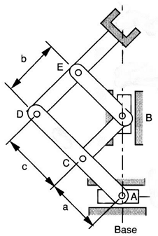
Q1. a. For the linkage shown in the figures, determine the number of degrees of freedom of the mechanisms.
b. Assume that you have a set of links with the following lengths: 20 mm, 30 mm, 45 mm, 56 mm, and 83 mm. check if it is possible to design a four-bar linkage that can be driven with a continuous-rotation electric motor. Justify your answer with appropriate equations. If the design is possible, make a freehand sketch of the resulting linkage. Label the crank, frame, coupler, and rocker (follower).
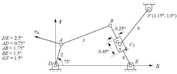
Q2. If the angular velocity of link 2 is 5 rad/s CCW, use the analytical method to find the angular velocity and angular acceleration of link 3, link 4, link 5, and link 6.
Q3. If the velocities of points A and B are as given in the rigid body shown. Find the point C in that link at which the velocity is zero.
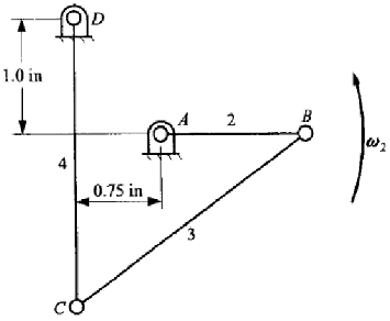
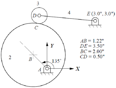
Q4. The circular cam shown is driven at an angular velocity ω2 = 15 rad/s (CW) and α2 = 100 rad/s2 (CW). There is rolling contact between the cam and the roller, link 3. Draw the velocity diagram and find the angular velocity of the oscillating follower, link 4. Use velocity scale 1 cm : 3 in/s.
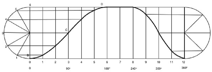
Q5. Construct the cam profile using the given displacement diagram. The cam is to have a radial roller follower with 20 mm diameter. The cam will rotate clockwise, and the base circle diameter is 80 mm. determine the maximum pressure angle.
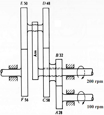
Q6. In the gear train shown, determine the angular velocity of the gear F.
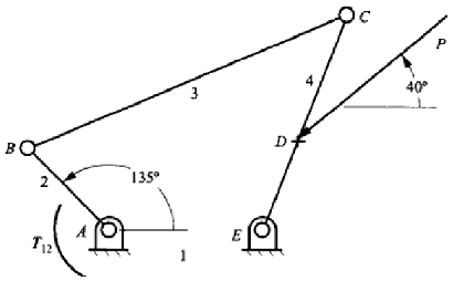
Q7. For the linkage shown in the figure, find the torque T12 required for the mechanism equilibrium if P = 100 lb in the direction shown. The linkage dimensions are as follows: AB = 6 in, EC = 12 in, AE = 8 in, BC = 18 in, ED = 5 in.