Reference no: EM132463326
SEHS3310 - Multidisciplinary Manufacturing Project - The Hong Kong Polytechnic University
Composites & Fabrication
Assignment 1 - Sheet Metal practice
Operation Description
Given that:
Material = Mild Steel
Thickness (T) = 1 mm
Inner Radius (R) = 1 mm
Angle of bend (A) = 90°
K-factor (K) = 0.4
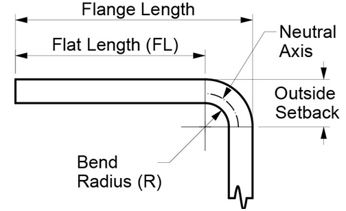
Outside Setback = (tan??A/2? )(R+T)
Bend Allowance (BA) = A(π/180)(R+(K×T) )
Flat length(FL)=Flange Length - Outside Setback
Total Development Width (TDW) =no.bends×(BA)+∑FL
Question 01: Production planning - Total Development Width
- Find the values of bend allowance and all flat lengths to determine the total development width of the material:
|
Plate thickness (T) =
|
1 mm
|
|
Bend radius (R) =
|
1 mm
|
|
Setback =
|
|
|
Flat length (FL-A) AND (FL-E) =
|
|
|
Flat length (FL-B) AND (FL-D) =
|
|
|
Flat length (FL-C) =
|
|
|
Bend allowance =
|
|
|
Total Development Width =
|
|
Table 1
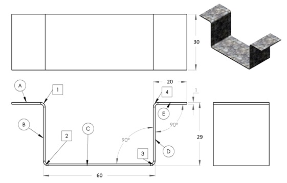
Question 02: Production planning - Development drawing
- Place above values onto Figure 1 dimension arrows (top of diagram) to indicate locations of Bend tangent lines
- Also, indicate bend tangent lines distance with respect to the plate edge (bottom of diagram)
Note: dotted lines indicate bend tangent lines on the backside of the plate.
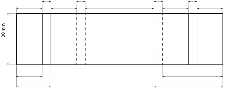
Figure 1
Question 03:
Production planning - bend sequence + sight line locations
- Refer to Figure 2 bend sequence, indicate the dimensions of sight lines on Figure 3
- Mark a ‘X' to indicate the position of the clamping jaw
- Note: dotted sight lines are marked on the backside.
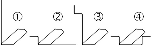
Figure 2
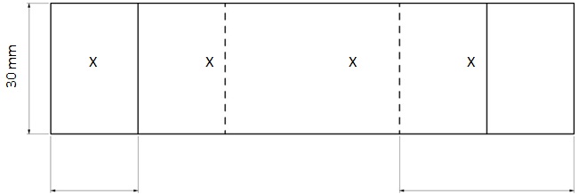
Figure 3
Question 04: Check-in of tools
- Check PPE, Hand Tools and Material are in good condition, use Table 2 below as reference.
|
Item
|
Description
|
|
1
|
Gloves
|
|
2
|
Deburr tool
|
|
4
|
Scribe
|
|
5
|
Engineering square
|
|
6
|
Divider
|
|
7
|
Steel Ruler (300mm)
|
|
8
|
160x100x1mm mild steel plate
|
Table 2, PPE, Hand tools & material list
Question 05: Material preparation - Shearing
- Set shearing machine clearance to correct material thickness.
- Trim material into 3 pieces as detailed in table 3
- Further trim 2x 30mm wide piece to the correct Total Development Width.
- Note: ensure all edges are deburred
|
Article
|
Specification
|
Remarks
|
|
Item 1
|
160 x 40 x 1mm
|
For 1mm radius shim.
|
|
Item 2
|
160 x 30 x 1mm
|
For 1st trial.
|
|
Item 3
|
160 x 30 x 1mm
|
For 2nd trial.
|
Table 3
Question 06: Marking sight lines
- Refer to Figure 3, mark sight lines on both 30mm wide plates
- Ensure sight lines are marked on each of the sides.
Question 07: Production of 1 mm radius shim
- Secure the 40mm wide plate in between the Pan Brake jaws, use the upper dials to correct for proper clamping pressure.
- Set bend leaf (lower dials) to 1 mm
- Bend the 40mm wide plate at R = 0 mm to approximately 130°
Question 08: Bending to production drawing
- Secure the 30mm wide plate (together with 1mm radius shim installed) in between the Pan Brake Jaws, use the upper dials to correct clamping pressure for 2mm thickness
- Set bend leaf (lower dials) to 2 mm to allow room for the additional 30mm wide plate,
- Align sight line to the radius tool,
Complete all bends with correct bend sequence.
Question 09: Dimension checks
with use on the flat table and Vernier calliper (to 0.02mm), measure the flange lengths and record results.
Question 10: Calculate the Total Development Width
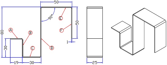
Figure 4
Given that:
Material = Mild Steel
Thickness (T) = 1 mm
Inner Radius (R) = 1 mm
Angle of bend (A) = 90°
K-factor (K) = 0.4
Find the values of bend allowance and all flat lengths to determine the total development width of the material:
|
Plate thickness (T) =
|
|
mm
|
|
Bend radius (R) =
|
|
mm
|
|
Setback =
|
|
|
Flat length (FL-A) =
|
|
|
Flat length (FL-B) =
|
|
|
Flat length (FL-C) =
|
|
|
Flat length (FL-D) =
|
|
|
Flat length (FL-E) =
|
|
|
Flat length (FL-F) =
|
|
|
Bend allowance =
|
|
|
Total Development Width =
|
|
mm
|
Table 4
Question 11: What is the difference between Sheet Metal and Machined parts?
Assignment 2 - Robotic arm design
Question 1: How many Degree of Freedom?? Why??
Question 2: What is the configuration (Grip type)?? Why??
Question 3: Sketch up your design (Free body diagram + dimension for each arm)
Question 4: What are your design details??
Assumptions: 1. The servo model is MG996R 2. The weight of load is 100g.
A. Calculation the maximum length of your arm
B. Any elements would affect your arm length? Explain it!
Assignment 3 - Solidworks design and drawings
Question 1: Take the below drawing as reference, draw your wheel configuration and fill the dimension
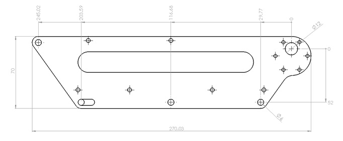
Question 2: Draw your design in SolidWorks with below sheet metal parameter.
P.S: You may download the question 1 drawings for reference.
Note: Change the radius to 0mm, bend deduction in 2.10 when thickness is 1.5mm, in 2.81 when thickness is 2 mm.