Reference no: EM132629570
Assignment 1: Op-Amp Comparator and Thermistor
Objectives:
After performing this experiment you should be able to,
1. Observe the resistance of the thermistor changes in relation to the temperature.
2. Construct a circuit using thermistor to measure the ambient temperature.
3. Construct a circuit using operational amplifieras a comparator, to turn ON/OFFa DC fan based on temperature.
Materials Needed:
|
1. NI ELVIS II+ workstation.
|
5. (1) 2N3904 Transistor.
|
|
2. (1) 10k? resistor.
|
6. (1) Brushless DC Fan.
|
|
3. (1) 10k? NTC Thermistor.
|
7. LEDs (1) Green and (1) Red
|
|
4. (1) LM741CN Op-Amp.
|
8. Connecting wires (as necessary).
|
Procedure:
1. What is the difference between NTC and PTC type of thermistors? Research online and write below your findings.
2. Apply +5 VDC to the given fan and measure the current. Remember to place Multimeter in series with the fan to measure the current. The measured current is ________.
3. Calculate the fan's resistanceusing ohm's law and record the result in table 1 below.
4. Measure the resistance of resistor and thermistor. Record the values in table 1 under measured value column.
|
Listed Value
|
Measured Value
|
|
Fan Resistance
|
|
|
Thermistor 10k?
|
|
|
Resistor 10k?
|
|
Table 1: Listed and measured values
5. Hold the top portion of the thermistor between two fingers (which causes raise intemperature) while measuring the resistance.
a. What happened to the resistance of the thermistor?
b. Release two finger and observe the resistance of the thermistor? Write below your observations.
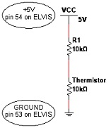
6. In order to convert change in resistance into change in voltage, construct the following voltage divider circuit.
7. Measure the voltage across the thermistor using DMM. The measured voltage value is _______.
8. What is the current room temperature in 0F___________ (use the in room thermostat)?
9. Usethe following formula to calculate the temperature in degree kelvin (ln is natural logarithm). The temperature in Kelvin is ___________.
T = (1/298 + 1/4038ln(V/5-V))-1
10. Convert kelvin to Fahrenheit using the formula below. Temperature in Fahrenheit is ______________.
0F = ((0K - 273.15)*1.8) + 32
11. Compare with the room temperature from step 8 with the value from step 10.What are your observations?
12. Hold the thermistor between two fingers while measuring the voltage across it. What happens to the voltage? Write your observations and reasons below.
13. From the circuit below, the reference voltage VREF = 2.2V is connected tothe non-inverting terminal of the op-amp. Calculate the reference temperature in degree Fahrenheit?Use the formula in step 9 andthen convert degree kelvin into Fahrenheit using step 10 formula.
The reference temperature is _______________ 0F.
14. Construct the circuit shown below on the bread board.
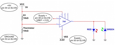
15. Set the Variable power supply +veto 2.2V and Supply -veto-5V.
16. Initially which LED is ON? Measure the output voltage and State the reasons below for such behavior.
17. Holdthe thermistor between two fingers. Now which LED is turned ON? Explain?
18. Now turn the power supply and prototyping board power OFF and disconnect both LED's. Keep rest of the circuit intact.
19. Research the datasheet of LM741CN. What is the maximum current capability of the IC Output short circuit current I = _______.
20. Referring to the step 2,can we used LM741CN to drive the fan directly? Explain.
21. What is the current capability of the transistor 2N3904. Research the datasheet. Icolelctor-current= _____.
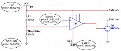
22. Add the following circuit using transistor.
23. Turn on the prototyping board power. RUN the variable power supplies. Is the fan ON or OFF? Provide reason for such behavior.
24. Hold the thermistor between two fingers. You may need to wait few secs in order to rise the temperature which was calculated in step 13. Is the fan ON or OFF? Provide reason for such behavior.
25. Turn OFF the prototyping board and variable power supplies.
Assignment 2 - Silicon Controlled Rectifier (SCR) Operation
Objectives:
1. To verify the operation of SCR using DC triggering.
2. To demonstrate the phase control operation of SCR using AC triggering.
Experiment Questions:
1. Before firing, the voltage from anode to the cathode is ___________.
a. 0 V b. Approximately Equal to VCC.
2. If the gate is made ________ when the anode and cathode are forward-biased, the SCR turns on.
a. Negative b. Positive
3. The SCR will _______ when the gate potential is removed and the anode/cathode are forward-biased.
a. Remain on b. Turn off
4. When the SCR is off, the voltage from the anode to ground is ________.
a. Close to VCC b. Near 0
5. The SCR will turn off when the current flowing through it drops below the _____________ value.
Attachment:- SCR Operation.rar