Reference no: EM13867136
Mathematical Modeling of a DC Motor
1 Objective:
The objective of this laboratory is to determine the mathematical model of a DC motor which will be used in the subsequent labs to control the velocity and position of a physical system.
2 Introduction:
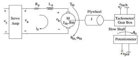
Figure: DC motor model for position and velocity control.
The purpose of this laboratory is to develop a mathematical model of a servo system from Feedback Instruments Limited. The main component of the servo system is the DC motor. The electrical model of the motor is shown in Figure. The DC motor is basically a torque transducer that converts electrical energy into mechanical energy. The torque developed on the motor shaft is directly proportional to the field flux and the armature current. Assuming that the field flux is constant, the motor torque can be written as
Tm = Ki * ia N.m
where ia is the armature current and Ki is the motor torque constant. When the current carrying conductor moves in the magnetic field, a voltage proportional to the speed of the motor is developed across the terminals of the motor (back emf) that opposes the current.
Therefore, the back emf, eb, can be written as
eb = Kb * ωm V
where ωm is the speed of the motor in rad/s and Kb is the back emf constant. In the SI units, the back emf constant is equal to the motor torque constant. However, if the SI units are not used, a conversion factor to relate the torque constant and the back emf constant
Ki (N.m/A) = 14.8Kb (V/rad/sec)
Now, writing the electrical equation using Kirchoff Voltage Law (KVL), we get
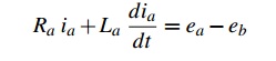
where ea is the applied voltage to the armature, Ra is the armature resistance and La is the armature inductance. Since the motor is driven by the servo amplifier, the armature voltage is given by
ea = Ksv * es
where es is the voltage applied to the servo amplifier and Ksv is the gain of the servo amplifier. If the flywheel is mounted directly to the motor shaft, the mechanical output of the servo-mechanism shown in Figure is given by
Tm = Jeθ¨m +Bmθ?m
where θm is the angular position of the shaft in radians, Bm is the viscous friction of the motor and Je = Jm + J + Jtg is the effective inertia that the motor sees. Note that Jm is the motor inertia, J is the flywheel inertia and Jtg is the inertia of the gearbox/tach attached to the motor. The output voltage of the tachometer, etach, is given by
etach = Ktach ωm
where Ktach is the tachometer constant. The position of the output shaft is given by
θo = θm/Ng
where Ng is the gear ratio of the gear box. The output voltage of the potentiometer, epot is given by
epot = Kpotθo V
where Kpot is the potentiometer constant. Note that the output shaft is the shaft of the gear box with a gear ratio of 30. The potentiometer is connected to the output shaft.
Pre-Lab Assignments:
1. Draw the block diagram of the servo system shown in Figure with es as the input; and tachometer and potentiometer voltages as the outputs.
2. Write the electrical time constant of the motor in terms of Ra and La, and the mechanical time constant in terms of Jm and Bm.
3. Find the following transfer functions: Etach/Es, and Epot/Es.
4. Assuming that the electrical time constant is much smaller than the mechanical time constant, simplify the transfer function Etach/
Es by neglecting the electrical time constant.
5. Assume that the term RaBm is much smaller than the term KiKb. Rewrite the transfer function found in part 4 and find the time constant of this transfer function.
6. etach and epot are the electrical quantities (in volts) which you will be able to measure in the lab. Given these quantities, please indicate the units (using SI) for the following system parameters: Ra, La, ia, ea, epot, etach, Ktach, Kb, Ki, Kpot, Tm, Jm, J, Bm, θm, ωm and θo.
In-Lab Assignments:
1. Use an impedance meter to find the resistance, Ra, and inductance, La, of the armature winding.
2. Find the inertia of the flywheel.
3. Set up the circuit shown in Figure 4.1 and collect the data in Table I.
Table I. Voltage versus Speed data to find Kb of the motor.
|
Input Voltage
|
Armature Voltage
|
Armature Current
|
back emf
|
Tach Voltage
|
Angular Velocity Slow Shaft
|
Angular Velocity of the motor
|
|
es (volts)
|
ea(volts)
|
ia(amp)
|
eb (volts)
|
Vtach (volts)
|
rpm
|
ωm (rad/sec)
|
|
0 V
|
|
|
|
|
|
|
|
0.2 V
|
|
|
|
|
|
|
|
0.4 V
|
|
|
|
|
|
|
|
0.6 V
|
|
|
|
|
|
|
|
0.8 V
|
|
|
|
|
|
|
|
1.0 V
|
|
|
|
|
|
|
|
1.2 V
|
|
|
|
|
|
|
|
1.4 V
|
|
|
|
|
|
|
|
1.6 V
|
|
|
|
|
|
|
|
1.8 V
|
|
|
|
|
|
|
|
2.0 V
|
|
|
|
|
|
|
|
2.2 V
|
|
|
|
|
|
|
|
2.3 V
|
|
|
|
|
|
|
|
2.4 V
|
|
|
|
|
|
|
|
2.5 V
|
|
|
|
|
|
|
4. Plot eb versus the motor speed ωm and find the back emf constant Kb.
5. Plot etach versus the motor speed ωm and find the tach constant Ktach.
6. Apply 1 volt input to the servo amplifier and record the tachometer output on the O-scope. Determine the transfer function, Etach(s)/Es(s) and the mechanical time constant of the motor.
7. Using the results of parts 4 and 6 and part 5 of pre-lab, find the effective inertia Je seen by the motor.
8. If the inertia of the gearbox/tach is 4.10-6 kg m2, find the inertia Jm of the motor
Report
1. Substitute the values of the motor parameters in the block diagram of the system drawn in the pre-lab and find the transfer functions Etach(s)/Es(s) . How does this transfer function compare with the transfer function obtained in part 6 of in-lab? If they are different, can you explain why?
2. Based on the results obtained, draw the block diagram for the speed control of the motor.