Reference no: EM132566948
ITEC40051 Wireless Communications - Nottingham Trent University
TITLE - Wireless Communication
Assessment Details
In your report, provide the answers and solutions to the following questions:
Q1. (i) Explain four advantages of digital versus analogue communication systems.
(ii) Explain what nonlinear quantisation mean and why and in which types of data a nonlinear quantisation is preferred to linear one.
(iii) Mention the structure of at least one commercial/popular application of nonlinear quantisation.
Q2. Explain
i) what the main advantages of MPSK (BPSK, QPSK, . . .) over other digital modulation systems (such as ASK, FSK, . . .) are, and what the benefit of using QAM is.
ii) what the difference(s) between bitrate and symbol rate is(are) and what the ratio between them for an 8-PSK is.
ii) what a "constellation diagram" refers to.
Q3. For a digital communication system,
(i) If the energy per bit is 12 dB and the noise level is 8 dB, what is the spectral efficiency?
(ii) If the channel bandwidth increases, what will happen to the spectral efficiency and Eb/N0.
(iii) In a binary communication system with an asymmetric transmitter, bits 0 and 1 are generated with 0.4 and 0.6 probabilities respectively. The receiver receives the bit stream of data through a noisy channel with the noise mean of zero and variance of 0.2. If the bit amplitudes for 1 and 0 are respectively 0.75 and -0.75, what will be the BER.
Q4. Delay is an important parameter in assessing the quality of a network. (i) Describe various causes of delay and (ii) explain how the long delays can cause information packet loss.
Q5. (i) Create a MATLAB Simulink model to implement the following modulation system.
y(t) = (1+mx(t)cos(3000t))
where x(t) is the 2000 samples (starting from the last 4 digits of your student number) of signal "speech" available in the "Data" subfolder of "Lab" folder of your Wireless Communication Module in NOW.
Hint: after you read the required data samples, normalise it to between -1 and +1; i.e.
x(t) ← x(t)/max(abs(x(t))
Provide a graph of the signal segment you used, Simulink simulation schematic, and the output y(t) for m = 0.1, 0.7, and 1.0.
(ii) Use the random binary source generator (such as Bernoulli) in Simulink to replace (1 + m x(t)) in the above equation with a binary signal varying between 0 and 1. Provide the input signal, Simulink schematic and the output. Which type of modulation is this?
Q6. (i) Explain the use of carrier sense multiple access (CSMA) in communication networks, explain what the cause of a possible collision can be when CSMA is used.
(ii) Explain the difference between CSMA/CD (collision detection) and CSMA/CA (collision avoidance).
(iii) Provide the CSMA/CA step-by-step procedure to prevent a collision in the network. Also, by further research, clarify how CSMA/CA can monitor the traffic within the network.
(iv) Using a basic CSMA, assuming the packet lengths to be 2 x 10⁻³ sec, and the channel capacity of 10 Mbits/sec. What should be the maximum propagation delay to maintain the network efficiency above 80%?
Q7. (i) Provide the advantages of CDMA (code division multiple access) over other multiple access channel sharing systems (e.g. TDMA, FDMA).
(ii) With the help of an example, explain how CDMA (code division multiple access) is used to multiplex three binary signals, each with 2 bits only. In your example use different spreading (chipping) codes of 8 bits each and show the process graphically as we practiced in the lectures.
Q8. This is to design a PSK (phase shift keying) system and assess the effects of number of constellation as well as communication channel.
(i) Use Simulink to design a Binary PSK (BPSK) communication system as in Figure 1.
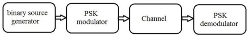
Figure 1
Use random binary source generator (you may use the source setup in your Lab 5 - Extra experiment) and AWGN (additive white Gaussian noise) as your channel effect. Use oscilloscopes and constellation maps to inspect the signals at right points of the system. Increase the noise level, draw the bit error rate (BER) versus signal to noise ratio (SNR), and specify at which noise level the demodulator is not able to recover the original signal accurately anymore. Draw your schematic and provide the constellation maps together with the input and output binary signals.
(ii) Use QPSK instead of BPSK in part (i). Demonstrate the results and compare it with those of BPSK. You may use the symbol rates similar to those suggested in the lab exercises.
Q9. Orthogonal frequency division multiple access (OFDM) is popular as a high-fidelity multiplexing system for wireless communication systems. Briefly describe the block diagram of the overall (transmitter - receiver) system, explain its advantages, and clarify why the OFDM system is an efficient modulation system.
Q10. For a line-of-sight (LoS) wireless transmission, the carrier frequency is 0.5 GHz and the distance between the transmitter and receiver antennas is 2 Km. In the transmitter we use a parabolic antenna with the face area of 0.8m2 and in the receiver an infinitesimal dipole is used. Considering the path loss and antenna gains, calculate the overall gain of the (transmitter- receiver) system in decibel (dB).
Q11. (i) Explain what transponders do in satellite communication systems
(ii) Provide the importance of evaluation of Link Budget is satellite communication systems and by doing some research explain various factors and parameters in the budget. Clearly explain what each block and its value/parameter refer to.
Q12. Here, an OFDM system is designed and evaluated. Using Simulink, setup the system according to Figure 2.
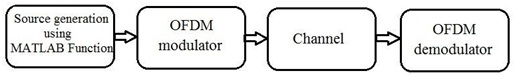
Figure 2
Select a four-path channel with discrete delays (0:4:12)*1e-6 Sec, average path gains of [0 -3 -6 -9] dB and sample rate of 50 KHz. Explain what the four paths can be related to.
(i) Use "MATLAB Function" in Simulink to generate a random complex-valued input as Data = complex(rand([256 4 1]), rand([256 4 1]));
Explain what the digits 4 and 1 in the Data argument refer to.
(ii) Apply orthogonal frequency division modulation/multiplexing (OFDM) to Data. Consider a Rician fading channel between the transmitter and the receiver. To evaluate the system for different fading levels, use constellation maps (why?) before the modulator and after the demodulator.
(iii) Explain how Doppler shift relates to mobile systems. Change the Doppler shift value in the "Channel" block from 0 to 150 Hz and compare the results for different settings.
Hint: For the OFDM modulator and demodulator you may choose discrete Fourier transform (DFT) length 267, number of guard bands [6; 5], and cyclic prefix length 16.
(iv) Change the data to
Data = complex(randn([256 10 2]), randn([256 10 2]));
Explain what the arguments [256 10 2] refer to and repeat (ii) and (iii). Can you still use constellation maps to view the data? Why? Try to find and explain a way to view and compare the input and output.
There might be few more variables to set for your Simulink modules/blocks. In order to do that refer to the settings you made during the lab sessions or decide yourself. Make sure you explain about your choices in each question/part.
Attachment:- Wireless Communications.rar