Reference no: EM132881475 , Length: word count:2500
Project
Instruction
• Students will use ANSYS Fluent software to solve heat transfer problems in this project.
• The report must be in the format of Microsoft Word file and submitted through vUWS. Reports in hard copy will not be accepted.
• Writing
The report will be assessed based on the accuracy of the results, discussion and writing. Input parameters must be given clearly. Figures should have clear captions and legends. You need to type formulae in your report. Copying formulae as pictures form books and lecture notes are not acceptable. You can use Excel to draw diagrams or tables based on the calculated results.
Problem definition
Fins are popularly used to control temperature of electronic devices such as chips. This project is aimed to find out the best configuration of the fins on a chip as shown in Figure 1. The air driven by a fan flows towards the fins from the top circular inlet and flow out of the domain from the four side boundaries. Figure 2 is the design of the fins. The key parameters are:
(note: the number b is the last digit of your student ID. If the last digit is 0, b=10)
• The surfaces of the fins and the chip totally release b Watts of heat.
• It is assumed that the heat flux is evenly distributed along all the fin and chip surfaces (excluding the bottom surface) shown in Figure 2.
• A fan is used to blow air into the inlet, and it is assumed that the uniform air velocity is b m/s.
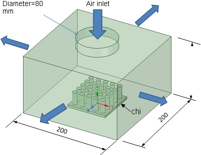
Figure 1 The setup of the whole fin system
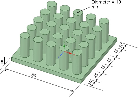
Figure 2 The design of the fins (unit: mm)
Assignment
1. Find out which of the follow configuration leads to the lowest temperature on the fins:
a. The air inlet is on the top of the box and four side boundaries are outlet boundaries as shown in Figure 1.
b. One side is a wall with the 80mm-diameter circular air inlet (same size as the inlet in Figure 1) and the opposite side is the outlet. The rest two sides are solid walls and top surface is solid wall. Income airflow is in the horizontal direction.
c. One side is a wall with the 80mm-diameter circular air inlet (same size as the inlet in Figure 1) and air flows through the rest three sides. The rest three sides are outlet boundaries and the top surface is solid wall.
d. One side is a wall with the 80mm-diameter circular air inlet (same size as the inlet in Figure 1) and air flows through the rest three sides and top surface. The rest three sides are outlet boundaries and the top surface is outlet boundaries (open).
2. Using the configuration shown in Figure 1 and moving the top boundary to 50 mm above the base level, find out if the performance will be improved.
Requirement
The report should be about 2500-word report.
You need to clearly specify the models you used to simulate the flow, the boundary conditions. You need to use pictures, diagrams and/or tables in your report to show the results.
You need to discuss where the maximum temperature is located in every configuration, explain physically how heat is transferred, discuss the uncertainty of the results, and give recommendations on the fin design.
Attachment:- Project.rar