Draw the state transition diagram for a second circuit

Assignment Help Electrical Engineering
Reference no: EM131176868

Reference-Value Definer with LCD Display

(a) Solve exercise 8.11 if not done yet. The reference values should be {000, 005, 010, 050, 100, 200, 400, 800}.

(b) Draw the state transition diagram for a second circuit, which should implement an LCD driver to have the reference value displayed on an alphanumeric LCD.

(c) Implement the complete circuit using VHDL or SystemVerilog and test it in the FPGA development board.

Exercise 11 in Chapter 8

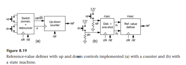
Arbitrary Reference-Value Definer with Up/Down Controls Figure 8.19b shows an alternative for implementing a reference-value definer with up and down controls, which is advantageous when the reference values are few and irregular (arbitrary). The first block was already treated in the previous exercise. Draw a state transition diagram for an FSM capable of implementing the second block, with eight reference values ( r1, r2, ... , r8). Recall that the inputs to this machine can only be x1x2 = " 00 "( idle), " 10 "( up), or " 01 "( down), with any nonzero input lasting only one clock period (as determined by the previous block).

1116_ac2ed0d6-b36d-48f8-b63e-bfaf37a5a998.png

Reference no: EM131176868

Questions Cloud

Implement this machine using the pointer-based technique : Implement this machine using the pointer-based technique and VHDL or SystemVerilog. Start by making the proper adaptations (using pointer(s)) in the state transition diagram. Create an array of constants to be placed at the output in states B and ..
Access to advanced technologies : Specifically, consider how working conditions, access to advanced technologies, and/or the health care consumer population might affect a health care professional's desire to work in the Baltimore area.
How the attacks affected risk management in organizations : Explain how the attacks affected risk management in organizations and have prompted an increased justification for recovery-based objectives, initiatives, and expenditures.
Describe the initial set-up of the market : (a) Describe the initial set-up of the market; (b) Analyse the effects of the local policy on the market in the short-run;
Draw the state transition diagram for a second circuit : Draw the state transition diagram for a second circuit, which should implement an LCD driver to have the reference value displayed on an alphanumeric LCD.
Initial choice of heating by an elderly individual : (a) Describe the initial choice of heating by an elderly individual; (b) Analyse the effects of an increase in the cost of heating on the consumption of heating and the well-being of that individual before and after the implementation of governmen..
How can you develop an informed perspective on the culture : In your health care work setting, what steps can you take to overcome barriers and provide care for a patient, if you encounter a cultural practice that you feel is unethical or with which you personally disagree?
What is the probability that none of the balls drawn is blue : A bag contains 2 yellow, 3 green and 2 blue balls.- Two balls are drawn at random. What is the probability that none of the balls drawn is blue?
Check whether the number of dffs inferred by the compiler : Recompile the code for N = 4 and simulate it using the same stimuli of figure 11.13a, checking whether the same results are obtained here.

Reviews

Write a Review

Electrical Engineering Questions & Answers

  Determine the value of the dc output voltage

A single-phase half-wave rectifier is fed with a triangular signal with period 2 . The maximum positive and negative amplitudes are ± 12 V rms. determine: a) The value of the DC output voltage. b) The percentage of curly

  Find the maximum value of ldb

If power Ps=10W, power gain factor G1=150, and power gain G2=14 dB, find the maximum value of LdB (path loss in dB) such that the power delivered to the resistor is -85 dBm.

  Design an adder using only multiplexers with one address bit

Given A=a1, a2, a3,a4 B=b1, b2, b3, b4 1) Design an adder using only multiplexers with one address bit.2) Design an adder using only multiplexers with two address bits.

  Why is one signal sensitive to noise and other one is not

How does noise affect the measurement signals in analog and digital data lines. Why is one signal sensitive to noise and the other one is not

  Calculate the composition of hgxcd1-xte which can be used

Calculate the composition of HgxCd1-xTe which can be used for a night vision detector with bandgap corresponding to a photon energy of 0.1 eV. Bandgap of CdTe is 1.6 eV and that of HgTe is -0.3 eV at low temperatures around 4 K.

  The differences between axial gap and radial gap permanent

the differences between axial gap and radial gap permanent magnet motors and between surface mounted and submerged

  Find what is the transfer function for a median filter

What is the transfer function for a median filter. Determine the step response for a 5-point median filter. Determine the impulse response.

  A mobile telelphone system mts has 10 channels operating

a mobile telelphone system mts has 10 channels operating at 30 khz with a max 80 kilometer range. what is the

  Design a cmos inverter taht has parameters voh

Design a CMOS inverter taht has parameters Voh=12V, Vol˜0, and Vic=4V, where Vic is the cross over voltage. Specify Vtr, W,and L for each of the MOSFETs for a minimum line width of 1.5 μm.

  Determine which output signal suers the worst delay

If Nand gates are used throughoutand a ripple-carry design is used, calculate the delay through the adder, assuming all inputs are presented at the same instant, and counting D seconds per gate. Which output signal suers the worst delay.

  If loop consists of loop what is the radius along the loop

A current of 4 A flows through a wire forming a "loop" circle of radius r. If the magnetic field in the center of the "loop" is 10 A, what is the radius along the "loop": a) if the loop consists of a loop of wire, b) if the "loop" consists of 20 t..

  Calculate the time delay required in pico seconds for signal

a transmission line is characterized by an effective signal wave frontvelocity of Vw=c/3. calculate the time delay required in pico seconds for a signal to propagate end to end on a line that is 30cm long.

Free Assignment Quote

Assured A++ Grade

Get guaranteed satisfaction & time on delivery in every assignment order you paid with us! We ensure premium quality solution document along with free turntin report!

All rights reserved! Copyrights ©2019-2020 ExpertsMind IT Educational Pvt Ltd