Reference no: EM131215964
Counter Applications - Stop Watch
Counters are a core building block to many circuits and systems. Counting circuits can be designed to count up or down. They can be made to begin at any count or end on any count, and can be reset. As was explored in previous labs, the counters can be either asynchronous or synchronous. Asynchronous counters have the advantage of simplicity, while synchronous counters have advantages with regard to speed and glitch avoidance.
Design Example - "Recycle" Up Counter:
Figure 1 displays a synchronous counter circuit that is designed to display a count from 0000 to 0110 (hex 6) and recycle. It utilizes the 74LS192 synchronous BCD/decade up/down counter with an active high reset.
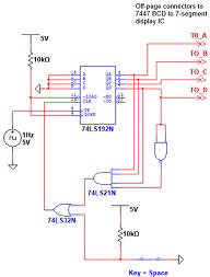
Figure 1: Synchronous Up Counter with Async Reset at 0111 (hex 7)
In this design example, the 4-input AND gate decodes the count of 0111 (hex 7), which is one higher than the desired count. When 0111 is reached, the output of the AND gate goes high. This activates the active high CLR input. Because the CLR input is asynchronous, the counter clears all outputs to zero within a few nanoseconds. The count of 0111 clears long before the next clock cycle, so the displayed count will recycle at 0110 (hex 6).
Design Example - "Recycle" Up Counter Using Load Capability:
A more generic way to design a recycle counter is to use the load capability of the 74LS192 to specify the starting value of the counter. When the LOAD and CLR inputs are both low, information present on the parallel data inputs (QD, QC, QB, and QA) is loaded into the counter and appears on the outputs regardless of the conditions of the clock inputs.
Figure 2 shows a synchronous up counter circuit that counts from 0001 (hex 1) to 0110 (hex 6) and recycles back to 0001.
Figure 2: Synchronous Up Counter with Asynchronous Load at 0111, and Recycle to 0001
In this design example, the 4-input NAND gate decodes the count of 0111 (hex 7), which is one higher than the desired count. When 0111 is reached, the output of the NAND gate goes high. This activates the active low LOAD input. Because the LOAD input is asynchronous, the counter loads the parallel data inputs within a few nanoseconds. The count of 0111 clears long before the next clock cycle, so the displayed count will recycle at 0110 (hex 6), then begin the count again at 0001.
Objective:
- To design a two-digit stop watch that counts up from 00 to 59 decimal and recycles.
- To design a two-digit stop watch that counts down from 59 to 00 decimal and recycles.
Parts needed for this lab:
- Function generator as clock source
- Push button switch with debounce circuitry
- Two 74LS192 BCD/decade up/down counter ICs
- Other TTL gates as needed depending on your final design
- Pull-up resistors as needed
- Two 74LS47 BCD to 7-segment display ICs
- Two 7-segment displays with 330Ω series resistors
Prelab:
Step 1 - Answer the following questions using the 74LS192 data sheet and the schematics in Figures 1 and 2. Answering these questions will help clarify what is needed for your stop watch designs.
- Which counter output is the MSB and which is the LSB?
- What are the logic levels on the output pins QN immediately following an active high signal on the CLR pin?
- Is the LOAD input synchronous or asynchronous to the clock?
- If DCBA = 1011, what are the logic levels on the output pins QN immediately following an active low signal on the LOAD pin?
- What pins need to be connected between the two 74LS192 ICs to cascade them? Specify both up and down counter modes.
- The examples in Figures 1 and 2 are both UP counters. What changes are necessary for the 74LS192 to act as a DOWN counter?
- What technique can be used to pause the counter?
Step 2 - Design a two-digit stop watch that counts up from 00 to 59 decimal and recycles. It must meet the following requirements:
- Can be reset to ‘00' at any point in the count.
- Uses a function generator as the clock source for the counter, with the frequency set appropriately such that the counter counts seconds in time.
- Includes a push button that can pause the count at any time with a single push, and restart the count again with a another push of the button. The push button must be debounced. The push button must not reset the count back to ‘00', but must restart the count from the point where it was previously paused.
- Uses two 7-segment displays to display the two-digit stop watch output.
Neatly draw the schematic for this circuit, complete with IC identifiers and pin numbers associated with each gate. Be sure it is a complete schematic for the circuit. Include the Boolean equation used to control the LOAD input and label each resistor with its value. The schematic must be organized into three pages by function to improved readability and organization:
- Debounced push button circuit
- Counter circuit
- 7-segment display circuit
The function generator may be shown as a box labeled "FG" to denote its input into the circuit.
Step 3 - Design a two-digit stop watch that counts down from 59 to 00 decimal
and recycles. It must meet the following requirements:
- Can be reset to ‘00' at any point in the count. Once reset, it must resume the count from ‘59'.
- Uses a function generator as the clock source for the counter, with the frequency set appropriately such that the counter counts seconds in time.
- Includes a push button that can pause the count at any time with a single push, and restart the count again with a another push of the button. The push button must be debounced. The push button must not reset the count back to ‘00', but must restart the count from the point where it was previously paused.
- Uses two 7-segment displays to display the two-digit stop watch output.
Neatly draw the schematic for counter portion of this circuit, complete with IC identifiers and pin numbers associated with each gate. Include the Boolean equation used to control the LOAD input. The function generator may be shown as a box labeled "FG" to denote its input into the circuit.
The schematic pages for the debounced push button circuit and 7-segment display circuit need not be repeated, as they are the same for both up and down stop watch designs.
Procedure:
Step 1 - Simulate the up stop watch from Prelab Step 2 in Multisim.
Demonstrate your results to your instructor. Save a copy of your Multisim schematic to print out for your lab report.
Step 2 - Simulate the down stop watch from Prelab Step 3 in Multisim.
Demonstrate your results to your instructor. Save a copy of your Multisim schematic to print out for your lab report.
Time permitting, implement the up stop watch in hardware.
Step 4 - Implement and test the up stop watch from Prelab Step 2. If it is helpful to you, you may create a wiring diagram for your circuit, but it is not necessary for your lab write-up.
To facilitate debugging, implement and test the hardware in functional blocks.
The following order is recommended:
- Pause circuitry
- First stage of the counter using LEDs to verify functionality
- Second stage of the counter using LEDs to verify functionality
- 7-segment display circuitry Demonstrate your results to your instructor. Results:
Your lab report for this lab consists of the following and is due at the start
of next week's lab period:
- Completed ELET215/CP215 cover sheet with name and date lab performed. A copy of the cover sheet can be found on Blackboard.
- Completed prelab, including any corrections made to the prelab during the lab period.
- A complete Multsim schematic for both up and down stop watch designs. Add a title to each schematic page and put your name and date on it. Each page of your schematic should be neatly labeled with the appropriate Boolean expressions, and inputs should be labeled so they can be easily recognized.