Reference no: EM132644981
Question 1. The structure below is loaded with the force as indicated. The critical components of the structure are Bar DF, BD and pin at D. The pin D is a double shear joint. The ultimate shear stress of the material is 300 MPa. Assume, safety factor on shear stress is 3. The cross-sectional area of the bars FD and BD are 2000 mm2, yield strength of the bar material is 210 MPa.
Find the following:
a. For the given information in the figure, calculate the required diameter of the pin for joint D.
b. The bars are made with a material that has yield strength of 210 MPa in tension or compression. Calculate the axial stress in bar DF and bar BD, and the safety factors for the bars.
c. Is the structure safe ?

Question 2. A column is fabricated from square structural steel tubing as shown in the figure, having a modulus of elasticity E = 210 GPa is subjected to axial loading. Determine the total change in length of the column.

Question 3. A state of plane stress consists of a tensile stress of σx=3 MPa, σy=5 MPa, and τxy=-7 MPa
a. Draw the original unrotated element and the corresponding 2-D Mohr's circle construction showing the x-face and y-face coordinates.
b. Calculate the principal stresses, σ1 and σ2 and their corresponding principal angles, θp1,θp2 and show all of these on your Mohr's circle construction and a properly oriented stress element.
c. Calculate the maximum shear stresses, ±τMAX and their corresponding angles of maximum shear stress, θs1,θs2 and show all of these on your Mohr's circle construction and a properly oriented stress element.
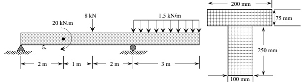
Question 4. A T-shaped cross-sectional beam is loaded as shown in the figure. Determine the following:
a. Sketch the internal shear force and bending moment diagrams for the beam.
b. Calculate the maximum magnitude of the bending stress. Indicate where this occurs on the cross-section and along the length of the beam.
c. Calculate the transverse shearing stress at the centroid of the cross-section using the maximum magnitude of the transverse shear force.
Question 5. Determine the state of stress at point A. Indicate the component of stress in the proper directions on the block provided. Is the state of stress indicated on the block a principal stress state?

Question 6. A beam is supported by ‘different support systems' as shown in the figures. Take, E and I as the beam constants. Find the deflection and slope equations of the beam for all three cases.
Note: Write down the boundary conditions, solve for reactions, solve for constants of integration, and then complete the deflection and slope equations.
