Reference no: EM131061702
Gear Box Design 2016
As an Engineer you will come across various designs to be completed during your career. This design work is intended to give you thorough understanding of steps needed to follow when designing different components which are common in the real world, use of standards and follow their procedures while designing and presentation of your work in solid modelling and orthographic drawings. Students individually design a mechanical transmission for individual operating conditions and individual gear box layout, present their calculation and design procedures in the form of a report, make use of solid modelling software to develop a solid model and produce working drawings of the transmission.
Project content:
Using Bonfiglioli software (available in computer classes) and initial data provided, explore possible concepts of the transmission and record additional data derived from the software. Using data acquired select and justify a concept for the transmission layout to meet operating conditions. Different students select different transmission concepts. Gather additional data from gearbox catalogues and Bonfiglioli Web-site.
Using kinematic and power / torque data determine forces in gearing. Determine forces acting on each shaft and support reactions. For shafts and gears: Select structural materials and recommend thermal treatment.
Carry out strength calculations (use Course notes and standard text books or Material Database for reference materials on gears). Select bearings (SKF software can be used for bearing selection and bearing support design, which can be found at:
(https://www.SKF.com).
For a specified component develop a manufacturing process (select machining methods and thermal treatment) without detailed calculations. Discuss measures to achieve the ease of manufacture. Discuss whether the same method of lubrication can be used for gears and bearings and specify seals and design elements related to lubrication.
Using solid modelling software (SolidWorks) develop a solid model and working drawings of the transmission designed (individually - not in a team). Print out several views of the solid model and attach it to the project report with your name on each printout. Each student prepares an individual project report.
On the title page of the report put project variant and name, gear layout and corresponding operating condition. Computational and descriptive parts of the report have to be supplemented with diagrams, sketches and drawings.
Solid model and drawings of the transmission will be assessed by a tutor that conducts solid modelling classes (submit a CD or USB with the solid model through the assignment minder by the submission date). Printouts of the solid model and drawings have to be attached to the project report to assess the conceptual design decisions.
After the title page make statement that the project has been carried out individually (except of the gearbox concept development) and all calculations have been carried out by the author of the project. Otherwise the project report may be a subject of plagiarism examination.
Operating conditions:
(i) Open-cut coalmine in tropical conditions. Dusty environment. Temperature range 20o to 45oC. and humidity 70 to 95%.
(ii) Arctic conditions. Clean environment. Temperature range - 40o to 0o C.
Gear Layouts:
(i) Two stage compound gear train or Two stage co-axial
(ii) Two stage bevel/cylindrical gear box Steps to be followed;
1. Selection of environment condition and layout of your choice
2. Select a variant from given variables [only 4 students can use one variable]
3. Use values provided in the variant to get initial design data such as input data and output data for the gear transmission
4. Based on these data select overall gear ratio and divide transmission into stages
5. Carry out kinematic calculations
6. Gear strength calculations
7. Shaft calculations
8. Bearing selection
9. Write a report based on your design calculations
10. Produce a solid model [parts, sub-assemblies, assemblies and housing] and drawings for your shaft assemblies and housing]
Variant 1:
Design of Machine Elements Gearbox design project variants
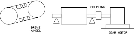
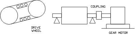
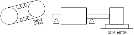
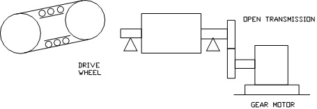
Design a Gearbox for a Horizontal Belt Conveyor shown in figure below
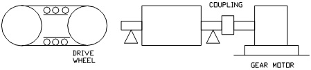
Belt length =25m; Capacity (dead load on belt) =1000t/h; Belt weight = 20kg/m; Roller Diameter = 40mm; Bearing diameter = 20mm; Drum diameter = 100mm; Lever arm of reaction force = 7; Travel speed = 2m/sec.
Variant 2:
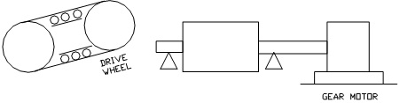
Design a Gearbox for a Horizontal Belt Conveyor shown in figure below
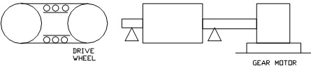
Belt length =20m; Capacity (dead load on belt) = 2000t/h; Belt weight = 10kg/m; Roller Diameter = 30mm; Bearing diameter = 12mm; Drum diameter = 150mm; Lever arm of reaction force = 7; Travel speed = 1m/sec.
Variant 3:
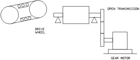
Design a Gearbox for a Horizontal Belt Conveyor shown in figure below
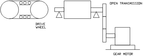
Belt length = 20m; Capacity (dead load on belt)=500t/h; Belt weight = 10kg/m;
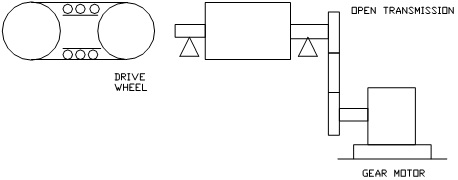
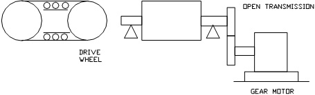
Roller Diameter=25mm; Bearing diameter = 12mm;Drum diameter = 150mm; Lever arm of reaction force = 6; Travel speed = 2m/sec; Diameter of driven wheel = 300mm; Diameter of drive wheel = 200mm; Efficiency for open transmission = 0.95
Variant 4:
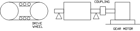
Design a Gearbox for a Horizontal Belt Conveyor shown in figure below
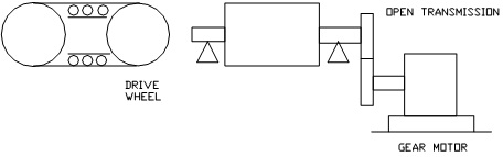
Belt length = 25m; Capacity (dead load on belt) = 800t/h; Belt weight = 15kg/m; Roller Diameter = 35mm; Bearing diameter = 12mm; Drum diameter = 200mm; Lever arm of reaction force = 7; Travel speed = 1m/sec; Diameter of driven wheel = 300mm; Diameter of drive wheel = 200mm; Efficiency for open transmission = 0.9
Variant 5:
Design a Gearbox for an Incline Belt Conveyor shown in figure below
Belt length = 40m; Capacity (dead load on belt) = 200t/h; Belt weight = 15kg/m; Roller Diameter = 30mm; Bearing diameter = 10mm; Drum diameter = 100mm; Incline angle = 10 degrees; Lever arm of reaction force = 6; Travel speed = 1m/sec.
Variant 6:
Design a Gearbox for an Incline Belt Conveyor shown in figure below
Belt length = 20m; Capacity (dead load on belt) = 300t/h; Belt weight = 15kg/m; Roller Diameter = 30mm; Bearing diameter = 10mm; Drum diameter = 80mm; Incline angle = 14 degrees; Lever arm of reaction force=6; Travel speed = 1m/sec.
Variant 7:
Design a Gearbox for an Incline Belt Conveyor shown in figure below
Belt length = 15m; Capacity (dead load on belt) = 200t/h; Belt weight = 15kg/m; Roller Diameter = 40mm; Bearing diameter = 15mm; Drum diameter = 90mm; Incline angle = 10o; Lever arm of reaction force = 6; Travel speed = 1m/sec; Diameter of driven wheel = 200mm; Diameter of drive wheel = 300mm; Efficiency for open transmission = 0.98
Variant 8:
Design a Gearbox for an Incline Belt Conveyor shown in figure below
Belt length = 20m; Capacity (dead load on belt) = 300t/h; Belt weight = 15kg/m; Roller Diameter = 30mm; Bearing diameter = 10mm; Drum diameter = 80mm; Incline angle = 14o; Lever arm of reaction force = 6; Travel speed = 1m/sec; Diameter of driven wheel = 200mm; Diameter of drive wheel = 300mm; Efficiency for open transmission = 0.98
Variant 9:
Design a Gearbox for a Horizontal Chain Conveyor shown in figure below
Chain length = 18m; Capacity (dead load on chain) = 2000t/h; Chain weight = 20kg/m; Pinion Diameter = 60mm; Sliding factor = 0.18; Travel speed = 2m/sec.
Variant 10:
Design a Gearbox for a Horizontal Chain Conveyor shown in figure below
Chain length =15m; Capacity (dead load on chain) = 1200t/h; Chain weight = 15kg/m; Pinion Diameter = 250mm; Sliding factor = 0.2; Travel speed = 1.5m/sec.
Variant 11:
Design a Gearbox for a Horizontal Chain Conveyor shown in figure below
Chain length = 10m; Capacity (dead load on chain) = 1000t/h; Chain weight = 20kg/m; Pinion Diameter = 100mm; Sliding factor=0.2; Travel speed = 1m/sec.; Diameter of driven wheel = 200mm; Diameter of drive wheel = 300mm; Efficiency for open transmission = 0.9
Variant 12:
Design a Gearbox for a Horizontal Chain Conveyor shown in figure below
Chain length = 15m; Capacity (dead load on chain) = 1500t/h; Chain weight = 15kg/m; Pinion Diameter = 250mm; Sliding factor = 0.2; Travel speed = 1m/sec; Diameter of driven wheel = 200mm; Diameter of drive wheel = 300mm; Efficiency for open transmission = 0.9
Variant 13:
Design a Gearbox for an Incline Chain Conveyor shown in figure below
Chain length =25m; Capacity (dead load on chain) = 700t/h; Chain weight = 15kg/m; Pinion Diameter = 100mm; Incline angle = 12 degrees; Sliding factor = 0.3; Travel speed = 2m/sec;
Variant 14:
Design a Gearbox for an Incline Chain Conveyor shown in figure below
Chain length = 25m; Capacity (dead load on chain) = 1000t/h; Chain weight = 15kg/m; Pinion Diameter = 300mm; Incline angle = 10 degrees; Sliding factor = 0.2; Travel speed = 1m/sec.
Variant 15:
Design a Gearbox for an Incline Chain Conveyor shown in figure below
Chain length = 50m; Capacity (dead load on chain) = 1000t/h; Chain weight = 10kg/m; Pinion Diameter = 250mm; Incline angle = 12 degrees; Sliding factor = 0.18; Travel speed = 1m/sec. Diameter of a driven wheel = 200mm; Diameter of drive wheel = 100mm; Efficiency for open transmission = 0.9
Variant 16:
Design a Gearbox for an Incline Chain Conveyor shown in figure below
Chain length =25m; Capacity (dead load on chain) = 1000t/h; Chain weight=15kg/m; Pinion Diameter = 300mm; Incline angle = 10 degrees; Sliding factor = 0.2; Travel speed = 1m/sec. Diameter of driven wheel = 200mm; Diameter of drive wheel = 300mm; Efficiency for open transmission = 0.9
Variant from 17 to 65 in attachment
Attachment:- Project variants.pdf