Determine and draw expected current and voltage waveforms

Assignment Help Electrical Engineering
Reference no: EM13885912

Analyze and design a boost converter and its controller given the following specifications:

An input voltage of 20V < Vin < 30V and an output of Vout = 50V over a load range of 10W < Pout < 100W. Switching frequency is fsw = 250kHz.

Hardware Design

1) Design the inductor (L) and capacitor (C). The current ripple ΔiL should be below 5% of the average inductor current IL at the maximum load under any Vin. The steady state ripple ΔVout is below 2% of the steady-state value of the output voltage. For the designed L, find the value of Iout,crit at the boundary of DCM and CCM. Plot Iout,crit vs. Vin.

2) For designed L, suppose there are four cores available listed below, select the core size to use the space maximum, design the inductor's number of turns N and the wire (use American wire gauge table) size.
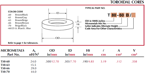
132_Analyze and design a boost converter.png

Steady-state Analysis

3) Analytically determine and draw the expected current and voltage waveforms for each component in your circuit at both light and heavy load.

4) Using PSpice/Matlab software, simulate the circuit under the heavy and light load conditions (provide schematic of the whole system). Plot the voltage and current of each component within 3 to 5 switching periods in the steady-state. Validate that the output of your simulation matches your analytical calculations in (2).

Modeling and Controller Design

5) Based on your designed circuit, considering the parasite resistance of the inductor r is 0.2Ω, using the average state-space method and small-signal technique to the transfer function v~o(s)/d~(s). Draw the open-loop bode plot of the frequency response (with matlab/pspice, not hand drawing).

6) Design a proportional-integral (PI) controller (recommend to use matlab siso toolbox) so that phase margin of the loop transfer function should be over 35o, and the crossover frequency is no larger than 10kHz. Provide the close loop bode plot (with matlab/pspice).

System Simulation

7) Using PSpice/Matlab software, simulate the designed circuit with controller, 1) Vin = 25 + 5*sin(2Π*60*t), simulate output voltage vo which should be a constant value, plot both Vin and vo in a same figure with time range more than 16.7ms; 2) measure the dynamic of the output voltage together with the disturbance of input or load through designing disturbances in load and input voltage. a) input voltage disturbances: Vin step change from 20V to 30 V; 2) load change from 10W to 100W. [Plot the disturbance, i.e., Vin, Load, and the output voltage of the converter in a same figure]

Write a report that documents that describes your results and observations from parts (1)-(7). Make sure all plots are well labeled and that explanations contain solid analytical foundations.

Make sure the figures are organized, neat and easy to be read and they are drawn by the software not by hand. Do NOT plot one graph per page.

Reference no: EM13885912

Questions Cloud

Estimate mass and weight of the air contained in a classroom : Estimate the mass and weight of the air contained in a classroom where Thermodynamics is taught. Assume the dimensions to be 3.2 m · 8 m · 20 m.
What was howard schultz''s original strategic vision : What was Howard Schultz's original strategic vision for Starbucks? How many times has his strategic vision changed or evolved into something different? Is his strategic vision for Starbucks in 2011-2012 likely to undergo further evolution?
Relationship between standard free energyand equilibrium : Give the relationship between standard free energyand equilibrium constant.The relationship between standard free energy and equilibrium constant is given by?GO= -R Tln(K)Where?GOis the std.
Prepare an assertive confrontation message : For each of the situations below, prepare an assertive confrontation message. Decide how you will phrase the basic message and further decide which additional components of the message you will use
Determine and draw expected current and voltage waveforms : Analyze and design a boost converter - analytically determine and draw the expected current and voltage waveforms for each component in your circuit at both light and heavy load.
Calculate pressure, density, specific volume, specifc weight : The temperature outside a house is -20-C and inside it is 20-C. What is the ratio of the density of the outside air to the density of the inside air? Would inflltration, which results from cracks around the windows, doors, and siding, etc., occur ..
Explain the interaction of technical and socio-cultural : Explain the interaction of technical and socio-cultural dimensions of project management. Are they related?
What pressure would needed to cause same decrease in volume : How high would 20-C water climb in a 24-mm-diameter vertical capillary tube if it makes an angle of 20- with the wall of the tube?
Paper- describing the value chain in your life : Write a (minimum two but no more than three pages) paper (not including title and reference pages) describing the value chain in your life

Reviews

Write a Review

Electrical Engineering Questions & Answers

  Determine the output of the system described by equations

Determine the output of the system described by the following difference equations with input and initial conditions as specified: y[n]+6y[n-1]-16y[n-2]=3x[n] x[n]=((-1)^n)*u[n] y[-1]=2 y[-2]=-1

  Calculate the rate at which the air is removing heat

A stream of air at 80 °F and 1.2 atm absolute flowing at a rate of 200 ft3/h is blown through ducts that pass through the interior of a large industrial motor. The air emerges at 500 °F. Calculate the rate at which the air is removing heat generat..

  What then is the indicated temperature

Suppose the RTD of (108.1 Ohms) has a dissipation constant of 25mW/°C and is used in a circuit that puts 8 mA through the sensor. If the RTD (108.1 Ohms) is placed in a bath at 100°C, what resistance will the RTD have

  Define addition of two numbers in ieee 754 format

Addition of two numbers in IEEE 754 format A) a=3f200000, b=be600000 B) a=3f200000, b=ff800000 C) a=01100000, b=80e00000

  Determine what voltage value will be measured

We can model the human body as a voltage source in series with a high resistance, let's say 10mV in series with 100kOhms. If we use an instrument with 1MOhm input resistance, what voltage value will we measure

  Determine the incident and transmitted angles

Light is incident from air to glass at Brewster's angle. Determine the incident and transmitted angles. Glass has refractive index n2=1.45.

  What current in amperes will flow through the bulbs

A 100 W bulb takes 0.833A and a 200 W bulb takes 1.67 A from a 120V source. If the two bulb were connected across a 240 V source, what current in amperes will flow through the bulbs?

  Series-tuned resonant circuit operates at a resonant

series-tuned resonant circuit operates at a resonant frequency of 1 mhz and contains a 0.1 microfarad capacitor and a

  What is the minimum regulator input voltage

1.)An op amp requires the design equation Vout = 5Vin & 2Vref + AgVg. What is the value of Ag 2.)The voltage dropout of a voltage regulator is 1.6 V. If a 16 V output is required, what is the minimum regulator input voltage

  Source transformation

Use Source Transformation to find V1 and V2?

  What functions must the communications stations perform

What functions must the communications stations perform? Repeat for ring and star.

  Write a report on future generation telecommunication

write a report on future generation telecommunication technology.5g technologies can amend the most high-bandwidth

Free Assignment Quote

Assured A++ Grade

Get guaranteed satisfaction & time on delivery in every assignment order you paid with us! We ensure premium quality solution document along with free turntin report!

All rights reserved! Copyrights ©2019-2020 ExpertsMind IT Educational Pvt Ltd