Reference no: EM133611873
Project to Design an Ultrasonic Signal Amplifier
Ultrasonic techniques have been widely utilised in various fields such as distance ranging, non-destructive testing, medical imaging and flow measurements. One example we frequently come across in our daily lives is the parking sonars of land vehicles to alert the driver of obstacles.
In a parking sonar system, the ultrasonic transducers with a centre frequency of 40 kHz are commonly used to transmit and receive ultrasonic waves. In the transmitting process, the ultrasonic transducer is driven by a high voltage signal and generates ultrasonic waves. The ultrasonic waves will be reflected by obstacles nearby and can be received by the ultrasonic transducers.
The received ultrasonic signals are usually weak, with peak-to-peak voltage amplitude (VP-P) typically in the range from 0.1 mVp-p to 10 mVP-P, determined by the distance between the ultrasonic transducer and the obstacles.
These weak signals will be amplified using ultrasonic signal amplifiers and then will be converted into standard digital signals (for instance, TTL signals) which can be further processed by digital circuits, such as a microcontroller like the Arduino. The time of flight of the ultrasonic signals will be measured by the microcontroller. As the speed of sound is known (e.g., approximately 343 m/s in air at room temperature), the separation between the vehicle and the obstacle can be calculated.
Ultrasonic signal amplifiers are essential for an ultrasonic system for at least two reasons. For one thing, they can significantly increase the amplitude of the received ultrasonic signals which are too weak to be converted into standard TTL signals. For another, they can be designed to have many advanced features such as incorporating bandpass filters to increase the signal to noise ratio of the ultrasonic signals, including a diplexer to enable one ultrasonic transducer to operate as both a transmitter and a receiver, and containing a time gain compensation (TGC) function to dynamically compensate for the attenuation of the ultrasonic wave.
The aim of this project is to design a basic ultrasonic signal amplifier for a parking sonar system. The received ultrasonic signal is a 10-cycle tone burst sine wave signal, whose centre frequency is 40 kHz. The amplitude of the ultrasonic signal is 5 mVP-P. The waveform of the ultrasonic signal (which is more complicated in reality) is shown in Fig. 5. You will develop the amplifier which can amplify the signal to a peak-to-peak amplitude between 4 VP-P and 5 VP-P. You will design, analyse and evaluate the circuit using the LTspice simulator.
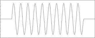
Fig. 5 An example of the waveform of a simplified ultrasonic signal
The peak-to-peak amplitude of the ultrasonic signal is 5 mVP-P, and the resistance (internal resistance) of the ultrasonic transducer is 550 ?.
The peak-to-peak amplitude of the output signal is between 4 VP-P and 5 VP-P.
A 20 M? resistor (the load) is connected between the output stage of the amplifier and the ground.
The waveform of the output signal is not distorted. Operates from a 15 V DC voltage supply.
You are strongly recommended to structure your report according to the marking scheme introduced in Section 2.4. The design, the simulation, the analysis and the evaluation of the circuit should be shown in the report. Your source files must be ready for simulation so please test them before submission.
Marking Scheme for Section
Introduction
Write an introduction to the project aimed at a non-technical audience. This should briefly set out the background, the motivation, the aims and the objectives of the project. Note that the emphasis is on writing in a style that a lay person would be able to understand.
Literature review
Before designing your circuit, carry out a literature review to find out about similar products. Try to discover:
why people use them;
what are the advantages of using an ultrasonic signal amplifier;
what are the design trade-offs;
what commercial products are available;
what are the key specifications for these products in terms of parameter types such as noise,distortion and anything else you can identify.
Identify a number of designs that you think are contenders for your project. Include a reference section at theback of the report to indicate your sources. Use the Harvard APA referencing system.
Description and analysis of your chosen circuit
When you have carried out the literature review and identified a suitable design, write in your report a clear and detailed explanation of how the circuit works in your own words. Any analysis and theoretical calculationwhich are needed to justify any aspect of the design should also be included.
Evaluation of your circuit
Evaluate the circuit through simulation to see if it meets the specification. You may also measure the voltage gain, the frequency response and any other parameter which your research has led you to believe may be relevant.
Tutor assessment of the circuit
The voltage amplitude of the output signal is within the targeted range for the given input signal.
The waveform of the output signal is not distorted.
The waveform doesn't have a DC offset.
Summary
Write a summary of the project aimed at a non-technical audience. You should summarise the work you havedone for this project design. You can also include conclusions and future work for this research. Note that theemphasis is on writing in a style that a lay person would be able to understand.
Quality of report writing and formatting/presentation
This includes the standard of the English grammar and punctuation, the quality of diagrams and tables, and the degree to which the report is well structured, enabling a reader to understand what you have done and why.