Reference no: EM131070222
Objective
Design a pixel for a next-generation 8KUHD display, including both the OLED and the drive transistor based off of supplied material parameters.
Introduction
Organic light emitting diodes (OLEDs) are widely used in mobile handsets and are being commercialized for next generation flat panel displays. OLEDs are efficient, and have faster response time, and higher contrast ratio (brightness difference between pixel on and off) than liquid crystal displays. Most modern display technologies use some form of thin-film transistor (TFT) based on amorphous silicon, or more recently, zincoxide to supply the current to drive each pixel.
Recently, high definition televisions have become very popular, with consumers demanding displays with an ever-increasing pixel density. TVs with a resolution of 1080p (i.e. 1,920 × 1,080 pixels) were impressive serval years ago, but now the new standard of 4K UHD (2160p / 3,840 × 2,160 pixels) is emerging. As an engineer for a major display company, you have been asked to look towards the future when 8K UHD (4320p 7,680 × 4,320pixels) displays will be the next hot thing. Your task is to see whether or not current OLED technology coupled to high performance Indium Gallium Zinc Oxide (IGZO) TFTs may provide a viable solution for the next generation of display technology.
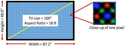
Figure 1: A 100" TV with corresponding dimensions for the standard HD aspect ratio of 16:9. Inset is a close-up of what one pixel based off of a PenTile array looks like, with individual red, green, and blue sub-pixels.
After a small amount of research, you have found that the average person sits ~10 feet from their TV. Knowing that pixel size is correlated to the size of the display, you you assume that 5 years from now, everyone will want a 100" display, as seen in Figure 1. You are also familiar with the photopic response of the human eye which is most sensitive to green light and you realize that the total area for all of the green subpixels should only be ~1/8 of the total pixel area.
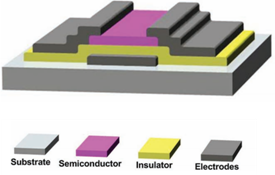
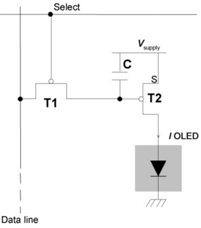
Because you are designing a pixel, you have to design the transistor to drive it. In display technology, the drive transistor for the LED is typically a Thin Film Transistor (TFT); its structure is illustrated in Figure 2(a). Two TFTs [T1 and T2 in Fig. 2(b)] serve to the select and drive the OLED.Figure 2(b) shows the circuit schematic for this arrangement. For a given OLED design, the transistor used to drive the OLED (T2) must also be carefully designed to match the OLED in order to deliver optimal overall performance.
Fortunately, you have access to recent literature, so you know that you can expect mobilities of~13and80 cm2/V-s for TFTs fabricated out of amorphous and polycrystalline IGZO, respectively. Through your reading, you have also noticed that a common channel width-to-length (i.e. W/L) ratio is ~5. Common materials for the gate dielectric are be hafnia oxide (HfO2, ?_r=25), aluminum oxide, (Al2O3, ?_r= 7~9), and silicon oxide (SiO2, ?_r=3.9 ). Your research has also shown you that the rail voltages (V_dd) for displays are typically 8 to 15 V.
The table below lists the typical values reported in recent literature for typical IGZO TFT parameters that will be helpful in designing your drive transistor:
|
Gate Dielectric Material
|
Dielectric Constant
(´ 0)
|
Channel Mobility
(cm2/V?s)
|
Threshold Voltage
(V)
|
|
Al2O3
|
6~9
|
6~10
|
4~5
|
|
HfO2
|
23~25
|
30~40
|
1~5
|
|
SiNx
|
6~7
|
15~20
|
1~5
|
Table 1.Typical range of parameters of IGZO TFTs
Before you begin, you have decided to refresh your memory with the important metrics for OLED pixels, asdefined below:
External quantum efficiency (EQE): This is the number of photons emitted and collected from the OLED per electron transported through the device. For monochromatic emission, the EQE is simply the measured optical power, L, divided by the photon energy (hv) and current, I. Because OLEDs have a finite spectral width, the EQE is given by the integral:
EQE(λ)=q/Ihc ∫λL(λ) dλ
The typical L-I-V measurement geometry is sketched below in Figure 2:
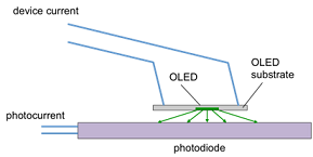
Figure 3: A typical OLED L-I-V measurement setup.
The OLED is situated in close proximity to a calibrated photodiode and a parameter analyzer is used to measure the device current (I) and photodiode current, IPD, as a function of bias voltage on the device. To convert the photodiode current to the optical power received by the photodiode, we use its wavelength dependent responsivity, R(λ), which is a calibration factor that tells how many amps of current flow for each watt of power incident on the photodiode. The optical power for light at a given wavelength is thus:
L(λ)=Kgeom (IPD S(λ))/R(λ)
whereS(λ) is the normalized electroluminescence intensity spectrum [i.e. ∫¦S(λ)dλ=1] and Kgeom is a geometry dependent calibration factor (i.e. depending on how much of the emitted light reaches the photodiode) that is ideally close to one.
Luminous power efficacy:This metric describes how many lumens are emitted from the OLED per electrical watt input to the device. The lumen is a photometric quantity that quantifies optical power as perceived by your eye. The optical watt is a radiometric quantity - the absolute power as defined by physics. For example, it is possible to have 1 W of optical power from a green laser and from an infrared laser, however, only the former carries any luminous power since your eye doesn't have any response in the infrared (that is, you don't see the infrared beam).
In order to convert from the radiometric optical power measured by the photodiode [L(λ)] to the luminous optical power, we use the photopic response (luminosity) function, g(λ) according to:
Plum=∫g(λ) L(λ)dλ
Given the device current and operating voltage, the luminous power efficacy is then:
ηP=Plum/IV
which has units of lumens/watt.
Brightness: How bright a light source looks depends not only on how many lumens it outputs, but how much of that power goes in a specific direction. This is quantified by the candela, which is defined in units of lumens/steradian (steradians are the units of solid angle - that is, angle in three dimensions. So, where there are 2π radians in the unit circle, there are 4π steradians in the unit sphere). For example, you can have a light bulb and a laser outputting the same luminous power, but you certainly don't want to look directly into the laser because all of that power is concentrated in a single direction!
To obtain the OLED brightness, we have to know the angular distribution of its emission. Because OLEDs are planar devices, a typical approximation is that they emit in a Lambertian distribution - where the intensity is proportional to the cosine of the emission angle relative to the surface normal (i.e. perpendicular to the surface). Integrating the Lambertian distribution over the forward emission half-space gives a total of π steradians.
The brightness, or more precisely the luminance, of the OLED (often referred to as ‘nits' in the display industry, units are cd/m2) is then given as:
Q= Plum/(π A)
whereA is the OLED active area.
OLED Data
A colleague in the OLED fabrication group has provided data for their new green OLED along with other useful information (see spreadsheet Green OLED Data.xlsx).
1. Given that the size of the test green OLED is 5 mm x 5 mm, calculate and plot its current density as a function of voltage, on both linear and log-log axis.
2. Using the photodiode responsivity data provided to you (obtained from the photodiode manufacturer), calculate the EQE and plot it as a function of current density using a semilog scale (that is, plot EQE versus the log of the current density). Assume that Kgeom = 6.7. Assuming that only 20% of the light emitted in the OLED comes out of the glass (a typical value), you can estimate your internal quantum efficiency (IQE), which is the total number of photons emitted per electron. What is the maximum IQE that your OLED achieves?
3. Using the luminosity function data provided to you (or you can look it up online), calculate the brightness of your OLED and plot it as a function of voltage. The typical brightness required for a pixel in your computer screen is ~100 nits. What voltage would be required from your OLED to achieve this? What current density does this correspond to?
4. Calculate the luminous power efficacy and plot it on a semilog scale versus brightness (i.e. plot η_P vs. the log of Q). What is the efficacy of your pixel at computer screen brightness (100 cd/m2)? What about at room lighting brightness (~1000 cd/m2)? How does this latter value compare to the luminous efficacy of a typical incandescent lightbulb?
Design of an OLED pixel for an 8K UHD display
5. Estimate the total pixel height, width, and area for a 100" 8K UHD TV. Next, estimate the total area required for green subpixels. Explain any assumptions made.
6. Using your answer from question 5, determine the total area allotted for your IGZO drive transistor.
This area will serve as the constraint for the design of the drive transistor.
7. Based off of your results from questions 3 and 5, what is the absolute current required to drive the green OLED subpixel at 100 nits? Ignoring any power dissipation caused by the transistor, how much power will a single green OLED subpixel dissipate? If all of the green sub-pixels in the TV were turned on, how much total power would they all dissipate?
The current needed to drive the OLED subpixel at 100 nits is defined as the requirement for the current of your drive transistor.
8. Before you start designing a new TFT to drive the OLED, you decide to first check whether there is any existing transistor that might provide you with some insight. You are able to obtain a prototype ZnO TFT and its data sheet, fabricated by other colleagues previously. However, the careless colleagues of yours have failed to deliver you with some of the important parameters of the transistor. Below is the data sheet you have at hand:
|
W / um
|
L / um
|
Gate Dielectric Material
|
Dielectric Constant
|
tox / nm
|
Channel mobility / / ( )
|
Threshold Voltage / V
|
|
200
|
20
|
Al2O3
|
8
|
32
|
|
|
In order to decide whether this ZnO TFT design could be used to satisfy the requirements and constraints for the OLED, you need to extract the missing parameters. Luckily, you've been well equipped with the essential techniques to conduct measurements on the transistor, therefore you are able to obtain the Id-Vd as well as Id-Vg data of this device, plotted as the following:
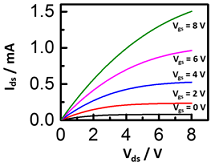
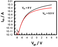
Assuming that the basic square law MOSFET equations apply for the current:
Linear region:
Ids= (WCox μn)/2L [2(Vgs- Vth )· Vds- Vds2 ]
Saturation region:
Ids= (WCox μn)/2L [(Vgs- Vth )2 ]
you should be able to extract the threshold voltage and channel mobility for this prototype transistor and fill them in the data sheet.
9. Now, with the area constraints imposed by your answer to question 6, as well as the drive current requirements obtained from question 7, using the parameters you've obtained for the above ZnO TFT in question 8, determinewhether you can design this TFT with width and length values thatwill deliver sufficient current in saturation to drive the OLED sub-pixel?
10. An alternative to the ZnO TFT you considered in question 9 are TFTs based on an indium-gallium ZnO (IGZO) channel. Based on the typical parameters for IGZO TFTs displayed in Table 1, you realize that this TFT technology may provide more leeway in your pixel design. Assuming the square law current equations hold, use the parameters in Table 1 to design an IGZO TFT that will satisfy the area constraint and drive current requirement for the OLED sub-pixel and write them in the table below.
|
W / um
|
L / um
|
Gate Dielectric Material
|
Dielectric Constant
|
tox / nm
|
Channel mobility / / (V.s )
|
Threshold Voltage / V
|
|
|
|
|
|
|
|
|