Reference no: EM131014985
Question 1 - Figure 1 shows an impression of one of the lifting arrangements produced and used at a metal fabrication workshop. It was manufactured to lift a maximum of 100 kg and due to a product line changes, it needs to be modified to lift a maximum mass of 150 kg. Due to this change, the factory manager needs to know whether the present lifting crane can be modified as quickly as possible using only the left over pipe pieces that had been purchased to manufacture the original lifting cranes. Your task is to provide the Manager with a suitable proposal.
The required design constraints are as follows:
Function of the existing cranes:
A loading block is attached as shown to Pipe at the end B. The load will be raised from the floor level to a height of 3 metres. Do not consider the geometry of the load at this stage. Pipes are attached rigidly to the WC500 column of a workshop building at point A and C. The corners of pipes at joint B rigidly welded together.
Available materials for modifications:
Materials: Four 2m lengths of 20 mm (OD)/16 mm (ID). (Ultimate Strength 250 MPa, Shear Strength 187 MPa, E= 200 GPa, Poisson's ratio =0.3, Density 7880 kg/m3)
Design Criteria:
Part 1-1 Analysis of existing crane arrangement - (Manual Calculations).
1. Start with the analysis of existing crane arrangement for rated load of 100 kg (+ 25% rated capacity). Next perform the analysis of existing arrangement (without any modifications) for extended capacity 150 kg (+ 25% rated capacity).
2. Identify the failure mode of the crane due to extended loading.
3. Only hand calculations by using fundamental formulas will be accepted. Use your fundamental knowledge in Stress Analysis (pre-requisite MEC2402 or equivalent). Strictly, do not use design formulas provided in design calculations, software or standards. Use suitable assumptions where required.
4. You have to list all your assumptions and highlight them. You are free to make justifiable assumptions to resolve statically indeterminate situations or problems. You also need to write and identify the parameters used in your fundamental equations.
5. Provide suitably neat hand sketches where necessary.
6. Provide your calculated results (stresses etc) using an appropriate presentation method (tabulate, lists etc)
Part 1-2 Analysis of crane with the proposed modifications - (Manual Calculations).
Design Limitations:
The overall size of the crane must not be changed. The modification will not extend outside the marked are in the figure1. The height and reach of the loading point is to remain the same. Original parts must remain and you are allowed additions such as corner plates, bracing, casings, ribs, enclosures for reinforcing etc. Due to frequent extreme overloading of crane by factory floor workers , the stress levels of major structural components of the crane needs to be kept under 75 MPa wherever possible. . If you can't maintain the max, stress level under the specific level, you need to justify it. Also you need to limit the vertical and horizontal displacement at the loading point less than 20 mm.
1. Start with the analysis of existing crane arrangement for proposed rated load of 100 kg (+ 25% rated capacity) with the proposed modifications.
2. Only hand calculations using fundamental formulas will be accepted. Use your fundamental knowledge in Stress Analysis (pre-requisite MEC2402 or equivalent). Strictly, do not use design formulas provided in design calculations, software or standards. Use suitable assumptions where required.
3. You have to list all your assumptions and highlight them in the report. You are free to make justifiable assumptions to resolve statically indeterminate situations or problems. You also need to write and identify the parameters used in your fundamental equations.
4. Provide suitably neat hand sketches where necessary and the final proposal must be sketched clearly. CAD packages can be used to present your design, but clearly define features with comments where appropriate. You are free to assume general engineering workshop processes are available for implementation of your modifications.
5. Provide your calculated results (stresses etc) using an appropriate presentation method (tabulate, list etc)
6. Calculate required lengths of materials and provide a cutting list.
Part 2 (Use Creo 3.0 Simulate for FEA analysis)
Create a suitable model with beam elements and perform an FEA for:
1. Existing crane arrangement with rated load i.e. 100 kg (+ 25% rated capacity)
2. Existing crane arrangement with extended rated load i.e. 150 kg (+ 25% rated capacity)
3. Crane arrangement with the proposed modifications with extended rated load i.e. 150 kg (+ 25% rated capacity)
Your need to provide usual FEA details i.e. complete picture of FEA model showing constraints, applied loads, number of elements and nodes, analysis type, element types, material properties, and other related details and you need to justify your FEA analysis based on manual calculations. Also:
• Tabulate necessary/critical stress levels and location before and after modification. You need only to show necessary stress/strain/displacement plots from Creo2.0 to justify your analysis.
• Conclusions on your design/modification.
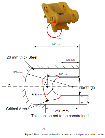
Question 2 - A heavy steel manufacturing company has designed and manufactured a "Quick Coupler" for earth moving equipment and put on it for field trials. During the trial period, there were frequent complaints from the customers about critical cracks formation around the curved surface of the coupler. A design engineer decided to perform a detailed stress analysis around the curved surface of the "Quick Coupler". The design engineer has chosen a representative portion of the quick coupler's critical area which includes the locations of cracks as shown in Figure 2b.
Your Task:
You need (assuming yourself as the design engineer) to perform FEA analysis using Creo3.0 Simulate to estimate critical stress levels at curved surface under operational conditions. It was observed that the inner edge points of the lips (as shown in Figure 2b) were displaced by 2mm (approx.) The coupler was made with steel. (Use appropriate values for mechanical properties of Steel)
1. Perform a detailed FEA analysis on Creo 3.0 Simulate for the portion of the Quick Coupler with suitable constraints.
2. Estimate manually, the stress level using your knowledge in "Stress Analysis". Use only the given dimensions, and list clearly your assumptions and justify them.
3. Tabulate and compare FEA results with manually calculated values. Explain and justify the differences (if there is any) in the answers you determined from FEA and manual estimates).
4. Conclude your investigation using your manual calculations and FEA results.
5. You need to provide appropriate stress & strain pictures to justify your conclusion in addition too usual FEA report details.
Question 3 - a. Using the stiffness method, determine the axial forces within members and the deflections of the joints of the truss shown in the Figure 2. The truss was built using 75 mm x 75 mm x 6 mm SHS with E= 200 GPa (approx). Show local stiffness matrices for each member and the assembled global stiffness matrix. Show your step by step solution. Use a convenient method to solve the matrix (e.g. inverse matrices). (Cross members AC and BD are not connected at the middle).
b. Perform an analysis for the truss using Creo 3.0 Simulate (Beam Elements) and list the solution's i.e. axial forces and the displacements. Tabulate manual calculations and FEA results for member forces and displacements. Compare your results with the manual calculations.