Reference no: EM132368914
Assignment
Objectives:
To model and investigate using Computational Fluid Dynamics, the flow past circular cylinder.
Apparatus:
ANSYS Fluent /CFX will be used as currently available at UTS.
Problem:
The overall dimensions of the rectangular box will depend on the diameter of the circular cylinder.
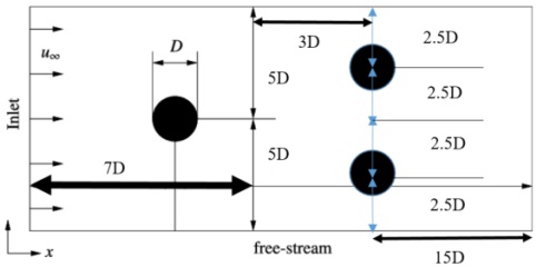
Fig 1: Schematic of the computational domain
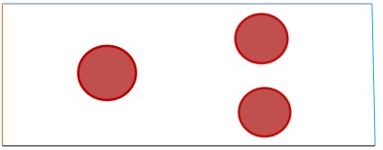
Fig 2: Name selection and boundary conditions.
The fluid flowing through the rectangular domain is air, with the following properties at 20°C:
Density, ρ = 1.2 kg/m3
Dynamic viscosity, μ = 1.81 x 10⁻⁵ Pa.s
The boundary conditions for all the CFD models are:
Inlet velocity, U∞= 1 m/s; 3 m/s; 5 m/s
Outlet Pressure = atmospheric pressure
Velocity at walls = 0 m/s (no slip)
Flow = Turbulent using default settings.
Procedure and discussion points:
1. Create a geometry in DesignModeler/ Solidwroks/any CAD software
2. Build an appropriate mesh for the model. This will necessitate to run the simulations and make a grid refinement study presenting the results for different grids for U∞ = 5 m/s.
3. Using the converged grid, for U∞ = 3 m/s, check the iterative convergence.
4. Using the converged grid, run CFX/FLUENT for U∞ = 1 m/s, 3 m/s, and 5 m/s.
5. Chart the axial velocity profiles u(y) at the leading edge, at mid, at the trailing position of the FIRST cylinder and discuss your results.
6. Plot the velocity contours for U∞ = 1 m/s, 3 m/s, and 5 m/s and discuss the flow characterization.
7. Plot the velocity vector for U∞ = 1 m/s, 3 m/s, and 5 m/s and discuss
8. Plot the pressure contour for U∞ = 1 m/s, 3 m/s, and 5 m/s and discuss your results.
9. Calculate the drag and lift coefficient for U∞ = 1 m/s, 3 m/s, and 5 m/s and plot the results.
10. Verify your results with the existing literature.