Reference no: EM1373258
Please note
You are required to write a formal report. As there is a guideline in end. The solution file just contains the report as per guidelines mentioned in end.
Introduction
In Amplitude Modulation, the amplitude of the carrier is varied by the message x(t) whereas in Angle Modulation, the angle of the carrier is varied by the message x(t). In order to improve the S/N ratio in Amplitude Modulated signals, the transmitting power has to be increased. In Angle Modulated systems the S/N ratio is higher than AM systems, however, at the expense of bandwidth. Angle Modulated signals are less susceptible to non-linearities than are Amplitude Modulated signals (since their amplitude is constant). The advantages of Angle Modulated systems over Amplitude Modulated ones has made them very popular, especially for applications where
(i) non-linearities may be present
(ii) an improved S/N ratio is required without the need to increase the power
(iii) the bandwidth expansion (not applicable for NBFM or NBPM) can be tolerated.
FM GENERATION
In angle modulated signals, the instantaneous phase (PM) or frequency (FM) varies linearly with the message signal. Two commonly used methods for FM generation are:
(a) Direct method: Uses a voltage controlled oscillator (VCO), whose oscillation frequency has a linear dependence on applied voltage (e.g.: an LC parallel resonance circuit).
(b) Indirect FM or Armstrong method: Uses a frequency multiplier and a NBPM or NBFM generator to obtain a WBFM signal.
Required Modules:
VCO, Envelope Detector Box, Multiplier, Adder,60kHz LPF andPhase Shifter modules.
1. Frequency Deviation Constant kf
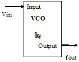
Figure 1-1VCO
The frequency deviation constant kf, also known as the deviation sensitivity characterises the transfer function of the VCO (Voltage Controlled Oscillator) Refer to Appendix 4 for more details. In this part of the experiment you will measure kf for the VCO module.
1.1. Power up the "TIMS" unit by using the switch at the back. You may use the picoScope for this section. Let the unit warm up for a while before taking measurements.
1.2. Set the DC output of the "Variable DC" module to 0V and connect it to the Vin input of the "VCO" module.
1.3. Set the "Hi Lo" switch on the "VCO" module to "Hi". Make sure that the switch inside the module is set to "VCO". Connect the "VCO" output to the Scope Selector and use the picoScope to measure the frequency of the the signal. Alternatively you can connect the "VCO" output to the "Analog" input of the frequency counter of the TIMS unit (set the "Gate Time" to 0.1 s).
1.4. Using the "fo" knob set the "VCO" output frequency to 100 kHz.
1.5. Set the DC output of the "Variable DC" module to 1.2V and adjust the "GAIN" control on the "VCO" module so that the frequency is 94 kHz. Once you have calibrated the VCO do not change the gain setting.
1.6. Vary the DC input voltage Vin between +2 and -2V in 0.5V steps. Observe and record the corresponding frequencies. Plot this data and determine the deviation sensitivity kf.

Figure 1-2VCO Transfer Function
1) Write a mathematical expression for the relationship between the input voltage and output frequency of the VCO
1.7. Apply a 1.25 V DC to the input of the "VCO module" and measure the output frequency. Also calculate the output frequency using kf and hence determine the percentage error between the calculated and actual frequencies.
2) Error = ___________
2. Frequency Deviation Df
2.1. Set theAudio Oscillator module's output frequency to 300 Hz and connect the output to the Vin input of the "VCO" module. Use the PicoScope to measure the message's amplitude (approx 2 V). On the picoScope change the Display mode to "Persistence mode". Set the timebase of the picoScope to 2ms and trigger from the output of the VCO. Since each cycle has a slightly different frequency, the waveform appears blurred. Calculate the peak frequency deviation using the procedure outlined in "Appendix 5".
3) Peak frequency deviation:____________Message Amplitude_______________
2.2. Compare the peak frequency deviation calculated above to the one calculated using the deviation sensitivity kf and the peak message voltage that you measured above.
3. FM Spectrum
3.1. Set the frequency of the Audio Oscillator module to 2 kHz, connect it to input A of the Buffer Amplifier module and connect the corresponding output k1A to the Vin input of the VCO. Gradually increase the input voltage swing whilst observing the spectrum of the VCO output (an FM signal). Set the spectrum analyser's span appropriately to allow you to see the spectrum around the carrier frequency.
3.2. Adjust the input voltage swing to a value that produces the first carrier null (i.e. Jo(b) = 0).
3.3. Observe and record the levels of all significant sidebands, reconciling your results with values given in the tables of Bessel Coefficients, and your preliminary work.
Figure 4-1 FM Spectrum
4) Compare the measured spectrum and the predicted one
5) What can be said about the spectrum as the amplitude of the modulating signal varies? (Note that fm is constant). How does it compare with Carson's rule of bandwidth estimation?
3.4. Set the modulating signal level to 4Vpp and increase its frequency to 10 kHz. Observe and record the magnitude spectrum of the VCO output.
3.5. Without altering the modulating signal level, reduce the modulating signal frequency to 300 Hz. Observe and record the magnitude spectrum of the VCO output.
Observed (10kHz) Observed (300Hz)
Figure 4-2FM Spectrum for 10 kHz and 300 Hz Messages
6) Compare the measured bandwidths of the FM signal with Carson's rule for these values of b.
4. FM Detection
A frequency detector, often called discriminator, produces an output voltage that varies linearly with the instantaneous frequency of the input. There are many different circuit configurations that can be employed and some of the most common classes are:
FM to AM conversion
Phase shift discrimination
Zero crossing detection
Frequency feedback (phase locked loops)
Figure 5-1 FM Detector below displays a typical FM demodulator that performs FM to AM conversion.
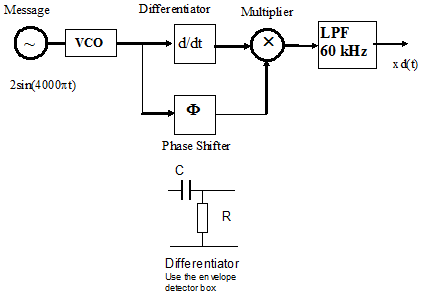
Figure 5-1 FM Detector
4.1. Set up the configuration of Figure 5-1 using the modules on the "TIMS" unit. Use a capacitor from the envelope detector box as the differentiator.
4.2. Adjust the phase shift so that the signal at the output of the LPF is maximised.
4.3. Observe and record the resultant output xd(t) in both the time and frequency domains.
Observed (Time Domain) Observed (Frequency Domain)
7) Has the message been recovered successfully? Discuss the results obtained.
5. Generation of Narrow-Band Phase Modulation (NBPM) Optional
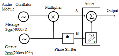
Figure 6-1 Narrowband PM Modulator
5.1. Connect the carrier signal to the input of the "Phase Shifter". While displaying both the input and output of the phase shifter on the picoScope, adjust the phase shift for F = 0o using the coarse and fine controls.
5.2. Using the appropriate "TIMS" modules set up the system shown in Figure 6-1 above.
5.3. Adjust the controls to produce a modulation index at the system output of about 0.3. To vary the amount of carrier injected, adjust the G and g controls on the Adder module. Note: this is a DSB-LC signal. WHY? (Use the spectrum analyser or the trapezoidal pattern on the CRO to set m.)
5.4. With the CRO triggered from the modulating signal, observe and record the output as the carrier phase, F is adjusted from 0o to 90o. Hint: Observe the amplitude variation of the modulated signal.
F = 0° (time domain) F = 90° (time domain)
What type or types of modulation are observed at a carrier phase of 90o? What did you expect?
5.5. Set the message frequency to 10 kHz,with the picoScope triggered externally from the carrier signal, increase the timebase to about 5ms./div. Measure the peak to peak phase deviation produced by this NBPM generator and hence deduce the modulation index b (F must be set to approximately 90o).
Modulation index b:______________________
5.6. Change the frequency of the modulating signal and observe if there is any change in the modulation index b.
5.7. Using the spectrum analyser and a few representative modulating frequencies, estimate the bandwidth requirements for a NBPM signal.
Modulating Frequency 1 Modulating Frequency 2
How does the measured bandwidth compare with the estimated one using Carson's rule?
Report Guidelines
Section Some issues that you should consider in your report
(These are minimum requirements. Express the ideas in your own words, don’t copy from the lab manual or your partner)
1. Title
2. Group members Title of Experiment
Names of your partners
3. Aims What are you trying to achieve from the experiment?
4. Theory What theory or background information is relevant to the experiment?
5. Experimental Method What equipment was used in the experiment?
What method did you follow?
6. Discussion of Results What results were obtained?
How do your results compare to the theoretical framework?
What do they mean?
How have you analysed/interpreted them?
Have you answered all the questions?
Were there problems that you experienced?
Can the method be improved?
Discussion of errors (quantify them)
7. Conclusion What did you learn from the experiment ?
What are you able to draw from your experiment?
8. References Acknowledge the source of the material that you have used