Reference no: EM131223816
Introduction
A Blowout Preventer (BOP) is being designed for an offshore drilling facility operating at a depth of 1300m. The drilling operation is from a floating platform rig where monitor and control of the BOP is conducted.
As a result of a hazard analysis, it has been determined that the "seal off well" function of the BOP is to be a Safety Instrumented System (SIS) in the form of a BOP Emergency Shutdown (BOP-ESD) System that must meet IEC 61508 Safety Integrity Level (SIL) of category 3.
The assignment involves undertaking concept control system design, PLC code development, SIL assessments, and RAM analysis to meet relevant system requirements.
Be sure to record any assumptions you have made in your analysis in an appendix to the assignment.
For context of the importance of the BOP in deep water drilling operations see https://www.youtube.com/watch?v=eOK9J0wETYo
System Overview
The system under consideration is defined as the BOP-PCS and is depicted in Figure 1 where the simplified system architecture of the overall system is given.
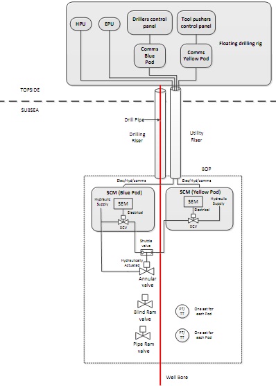
Figure 1: Simplified system architecture. Figure shows control scheme for one valve. Similar functions are used to control the other two valves.
Referring to Figure 1, the BOP control system consist of two control stations on the rig: the drillers control panel and the tool pushers control panel. Each control panel allows each operator to independently control each of the BOP valves i.e. Annular, Blind Shear Ram and Pipe Ram valves (the Pipe Ram Valve is also known as the Variable Bore Ram (VBR) valve). Each of these control panels are able to independently control BOP valves via its own communication network that is used to communicate control commands to independent Subsea Control Modules (SCMs) located at the subsea BOP.
The salient feature of the control system are as follows:
- Each SCM (Blue Pod and Yellow Pod) have independent electrical and hydraulic supply lines from the Electrical Power Unit (EPU)/Hydraulic Power Unit (HPU) through the utility riser. These are used to supply electrical power to the Subsea Electronics Modules (SEMs) located within each SCM and hydraulic power to control BOP valves.
- All BOP values are controlled by a single actuator using 5,000 psi hydraulic supply lines.
- Directional Control Valves (DCVs) are used to control the hydraulic supply to the valve actuators. An electrical signal from the SEM is used to open and close the DCV to direct hydraulic as required. DCVs are of the normally closed type (i.e. in the absence of sufficient electrical power, the DCV remains in the closed position where hydraulic fluid is prohibited from flowing from the hydraulic supply line to the valve actuator.
- A shuttle valve is used to allow hydraulic fluid to flow through it to the valve actuators from one of two hydraulic sources.
- All BOP valves are of the normally open type (i.e. in the absence of sufficient hydraulic power, the valves remain in the open position).
- There are two sets of integrated pressure/temperature transmitters (PT/TT) to detect pressure and temperature at two locations within the BOP. Each SCM pod interfaces to its own set of sensors. These sensors are used to detect a formation "kick" condition (i.e. extreme erratic pressures and uncontrolled flow emanating from the well reservoir during drilling. This condition represents a serious and hazardous condition to the drill rig and its operators). Each PT/TT interface to their respective SCMs via a 4-20mA analogue signal interface. The SCM then converts the analogue signal to a digital signal for transmission to the control panels for display to the driller and tool pusher operators.
- On detection of a "kick" operators are required to:
- First close the Annular valve to prevent the flow rising up the annulus region and up the drilling riser. This valve closes around the drill pipe.
- As a backup, in case the of Annular valve failure, close the Pipe Ram (or VBR) valve which also prevents the flow rising up the annulus region. This valve also closes around the drill pipe.
- If both these valves fail, the operators are required to close the Blind Shear Ram valve, which completely seals the wellbore, even when the bore is occupied
by a drill pipe. This is achieved by cutting through the drill pipe as the rams close off the well preventing flow up the drilling riser or the drilling pipe itself.
- There are independent control (i.e. digital data communications) lines from each of the SCMs to the topside control panels (via the topside communications interface). This allows SCM communications with the control panels for valve control and PT and TT data transfers.
TASK 1 :
Using candidate components listed above, provide a concept design for the BOP-ESD. Also, indicate and justify the fault tolerance levels used for the safety function.
For your design you can assume the following:
- There is sufficient space in the BOP to include at most one PLC and at most 2 DCVs.
- There is sufficient space in the BOP stack to include at most 1 additional Blind Shear Ram valve. If you decide the additional Blind Shear Ram valve is necessary, comment on and justify its preferred location within the BOP stack by considering common mode failures.
- There is sufficient electrical power and hydraulic power that can be obtained from existing BOP infrastructure to power all BOP-ESD components under normal operating conditions.
- All candidate components are classified as "Type A" or simple devices.
- The design should minimise component count but still meet all requirements.
Draw a RBD for the safety function of the BOP-ESD. Determine the PFD for the safety function and resulting SIL achieved. State the proof test interval required for the BOP-ESD components. All BOP-ESD components are to have identical proof test intervals. Use appendix B for relevant formulas.
TASK 2
Undertake RAM analysis to show if the BOP-ESD meets RAM system requirements. For RAM analysis purposes assume the following:
- The Mean Time To Repair (MTTR) for all subsea components in the event of the safety function activating is 2880 hours.
- All redundant items are non-repairable.
- Where the dangerous undetected failure rates are known for a component, then the residual failure rate (i.e. total failure rate minus the dangerous undetected failure rate) results in a fail safe condition for that component. Use appendix C for relevant formulas.
Note, the system is not fail safe, that is, the DCVs are normally closed and the BOP Blind Shear Ram value is normally open, so in terms of RAM analysis you will need to consider only those fault conditions that will cause the SIS to activate the safety function as a false positive.
TASK 3
Develop full PLC ladder logic for the logic solver to implement your SIS design based on the fault tolerance and redundancy levels chosen. Base your design on the same Omron PLC hardware (CPU and I/O modules) and development environment (CX-Programmer) as is used in the laboratories. Your design should consider the following:
a. The sea water pressure at a depth of 1300m is 1900 psi.
b. The PT that measures sea water pressure provides a 4-20mA output signal related linearly to a pressure range of 0 to 4000 psi. The load resistor used at the PLC for this PT 4-20mA input is 500Ω. This PTs has an accuracy (3σ) of ±0.5 % FS (max).
c. The PT that measures hydraulic supply pressure provides a 4-20mA output signal related linearly to a pressure range of 0 to 10,000 psi. The load resistor used at the PLC for this PT 4-20mA input is 500Ω. This PTs has an accuracy (3σ) of ±1 % FS (max).
d. The PLC analogue input module has a voltage input range of 0-10V.
e. The communications health detector provide a 0VDC digital low signal when the communications health status is "down" and a 24VDC digital high signal when the communications health status is "up". To avoid false tripping due to transient failures, the communications fault condition alarm should only be tripped if the status is "down" continuously for more than 20 seconds.
f. The PLC digital input module has a voltage input range of 0-24VDC.
g. When 0VDC is supplied to the DCV then the hydraulic pressure that is supplied to the valve actuator is low and the valve is in the open state. When 24VDC is supplied to the DCV then the hydraulic pressure supplied to the valve actuator is high and the valve is in the closed state.
h. The PLC digital output module has a voltage output range of 0-24VDC.