Op-amp Regulator Incorporating Current Boosting with Zener Reference:
For larger load currents, the simple regulator illustrated above has to be modified as illustrated in Figure wherein a Zener diode is utilized to create reference voltage and transistor Q1 has been added for increasing regulation action. Now, we have
V ref = Vz and V0 = (1+ (R f /Ri) V z
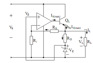
Figure: A Modified Op-amp Regulator
Design Example
Let V0 (required) = 15 volts DC we may design the circuit as follows.
(a) Select VZ, typically 1/2 or 1/3 of Vs, let VZ = 5 volts,
∴ RD = (V0 - Vs )/iD = 15 - 5 /5 mA = 2k
(Supposing that a current of 5 mA is adequate to cause breakdown of Zener diode.)
(b) Permit a current of 1 mA to flow in (Rf + Ri) so that :
(R f + R j ) = V0 / 1 mA = 15 /1 mA = 15k Ω
Since V0 =(R f + R j ) /Ri . Vz therefore, 15 = (15k / Ri) .5 gives Ri = 5 k and Rf = 10 k.
(c) Since Vs ≥ V0 + 2, we choose Vs ≥ 17 volts,
(d) Other design considerations :
(i) We select VZ and RD such that : (IRf + IRD) < < IL. Clearly,
IL (max) ≅ hFE I0 (max) = 50 × 10 mA ≈ 500 mA
(ii) Power dissipated in Q1 : PD = VCE (max). IL (max). Therefore, if
IL (max) = 500 mA; Vs (max) = 36, V0 (desired) = 15 volts, then,PD = (36 - 15) × 0.5 = 11.5 watts!!
obviously, appropriate heat sinking arrangements are required to properly dissipate the generated heat.
The above scheme may be further modified by incorporating 'current limiting' and 'overload protection' circuitry as we shall see in the following.