Series RLC Circuit:
The applied voltage is v = Vm sin ωt
Inductive reactance X L = ωL
Capacitive reactance X C =1 / ωC
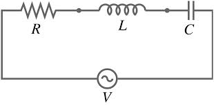
Figure: Series RLC Circuit
Here, we describe the impedance of the circuit which is given by
Z = R + j ( X L - X C ) in ohm
The magnitude of the impedance is
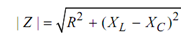
and angle
θ= tan -1 (X L - X C) / R
This is the angle between the applied voltage v and the current i. θ is also termed as the power factor angle of the circuit.
The current i is specified by
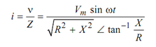
where X = XL - XC
or i = (Vm /| Z | ) sin (ωt - tan -1 ( X /R)
If the circuit in inductive (XL > XC) then current i lags the v by angle tan -1 (X/ R) . But if the circuit is capacitive then i leads the v by angle tan -1 (X/ R) .
The voltage drop across each passive elements
VR = i R, VL = XL i, VC = XC i
Also v¯ = v¯ R + v¯ L + v¯ C (Kirchhoff's Voltage Law)
Generally, if we apply Kirchhoff's voltage law in series RLC circuit then KVL equation is given by
v = R i + L di/ dt + (1 / C )∫ i dt