Half-Wave Rectifier:
If a diode and load resistor are connected in series with an AC source as illustreated in Figure, the resultant voltage v0 = i0 RL and current i0 through the load resistor RL shall be as shown. In drawing this waveform, we have supposed that the diode is ideal and therefore, have avoidd the 0.7 V drop while the diode conducts, and have supposed that the diode can be treated as an open-circuit when it is not conducting. Therefore, the circuit of Figure changes AC into unidirectional DC. The equivalent DC value of this voltage is given by
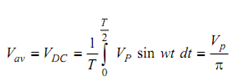 -------- (1)
where the applied voltage is v = Vp sin wt, period T = 1/f, and w = 2π f. As an instance, the average or DC voltage, if the applied voltage is 120 Vac, would be 120 × (√2 / π) or 54 V. The DC current passing through the load resistor RL is I DC = ( Vp /π) RL .
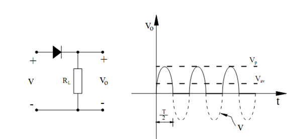
Figure: Half Wave Rectifier and Its Waveforms