Read/Write and Control Logic:
The function of this block is to manage all internal and external transfers of both Data and Control or Status words. This accepts inputs from the CPU Address and Control busses and in turn, issues commands to both Control Groups.
- (CS) Chip chooses. A "low" on this input pin enables the communication among the 8255 and the CPU.
- (RD) Read. A "low" on this input pin enables 8255 to send the data or status information to the CPU on the data bus. It essentially allows the CPU to "read from" the 8255.
- (WR) Write. A "low" on this input pin enables the CPU to write data or control words into the 8255.
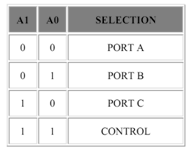
- (A0 and A1) Port Select 0 and Port choose 1. These input signals, in conjunction with the WR and RD inputs, control the selection of one of the three ports or the control word register. Normally they are connected to the least significant bits of the address bus (A0 and A1).
- (RESET) Reset. A "high" on this input initializes the control register to 9Bh and all ports (A, B, C) are set to the input mode.
Group A and Group B Controls
The systems software programs the functional configuration of each of the port. Essentially, the CPU "outputs" a control word to the 8255. The control word have information such as "mode", "bit set", "bit reset", etc., that initializes the functional configuration of the 8255. Each Control blocks (Group A and Group B) accepts "commands" from the Read/Write Control logic, attain "control words" from the internal data bus and issues the proper commands to its associated ports.