Longitudinal Profile Levelling
Now let the central line of needed route be ABCD as shown in Figure.
Note in which the change points A, B, C, D etc are about 30 m to 70 m apart, not more than 100 m in normal conditions. Staff intermediate stations, e.g. 1, 2, 11 etc. are commonly 5 to 20 m distant.
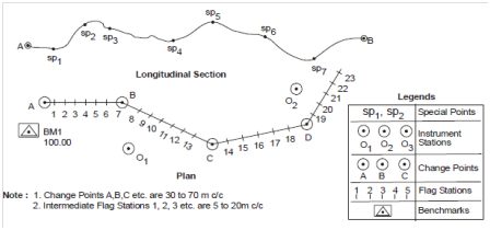
Figure : Longitudinal Profile Levelling
The instrument is set up at a appropriate firm ground (say O1), properly levelled and adjusted, from that large number of staff stations could be commanded. Backsight is then taken on the bench mark to determine HI, the decreased level of line of collimation at instrument station O1.
Staff readings are then taken beginning from station A followed through readings at predetermined intervals of 5 m or 10 m, measuring the distance A-1, 1-2 etc. through stretching the chain on aligned line AB. Further to intermediate stations 1, 2, 3 etc., readings are also taken at critical or important points on the ground, that is points denoting change of slope or other significant features (e.g. sp 1, sp 2 etc.).
While the length of line of sight exceeds visibility limit, e.g. about 100 m or so, or if there is a few obstruction in the line of sight, the instrument is needed to be shifted to new position (say O2). Foresight on staff station B is taken from instrument station O1 before shifting the instrument from position O1 to O2. While the instrument is set, levelled and adjusted at O2, the first reading recorded from O2 will be the backsight at B. This will decide the RL of newly build collimation plane. The distance of intermediate and special points are continued to be measured along line BC and levels read at every of these stations. Previously established benchmarks are important points on that staff readings are unavoidably taken as a check on level measuring process. Bench marks could also be used as change points.
To plot the longitudinal profile of the ground along the survey line, the first step would be to fix a datum line and marking the chainages of the intermediate, special and change points on it at a appropriate scale (Figure10). Vertical lines are then drawn on that chainage line at every intermediate, special and change points. The respective stages are then marked on these lines. The line joining these plotted points represents the longitudinal ground profile. In sequence to highlight the ground undulations, vertical scale is chosen various than horizontal scale. Generally, the ratio of vertical and horizontal scales is about 10. It could be observed in Figure in which chainage and levels at each station are written against the ordinates at stations.
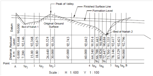
Figure : Typical Longitudinal Profile
Based on the longitudinal and cross sectional profiles and the needs of the project facility, a working profile is ready. The working profile of a highway is display in Figure . It is represented through double line; the lower line denotes the creating level while the upper line will give the finished surface profile. The map will then be able to supply data about
(a) Original ground level,
(b) Formation level,
(c) Finished surface level,
(d) Depth of cutting or filling,
(e) Proposed gradient, and
(f) Any other useful information needed for execution of the construction project.