Astable Multivibrator using Op-amp Comparator:
An astable multivibrator using an op-amp comparator is utilized to produce symmetrical square wave signal which is needed in many applications. For instance, if a square wave generator is available one may obtain triangular waveform by integrating square wave and from a triangular waveform, one may make a sinusoidal waveform by an appropriate wave shaping circuit such as, a triangular to sign wave converter. Therefore, a square wave generator can constitute an important building block of a function generator.
An astable multivibrator by using an op-amp comparator with positive feedback is illustrated in Figure, where op-amp along a resistors RB and RA may be seen to be configured as a Schmitt trigger. By analysis, it may be shown that this circuit may generate square wave whose time period may be set by proper selection of component values R, C, RB and RA.
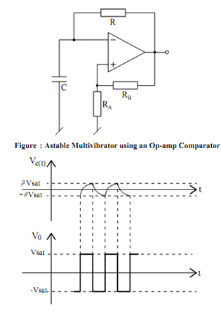
Figure : Various Waveforms for the Astable Multivibrator
For the analysis of this circuit, let us suppose that the output V0 = + Vsat. Therefore , It is seen that the input signal at the non-inverting input of the op-amp comparator shall be + β Vsat, where β = RA / (RA + RB) . Thus, the capacitor voltage Vc shall be charged exponentially towards + Vsat by time constant RC. Vc shall continue to grow until it becomes a little more than + β Vsat at which time the comparator shall switch to - Vsat.
The reference voltage at the non-inverting terminal shall now change to - β Vsat. As the capacitor voltage has already attained a value equal to + β Vsat it shall now try to discharge exponentially towards - Vsat. This shall continue until Vc attains a value equal to + β Vsat at which time the comparator shall again switch back to + Vsat. This procedure continues and the resulting wave forms of the capacitor voltage Vc and comparator output V0 shall be as illustrated in Figure It may be noted that since the charging and discharging, both are occur with the same RC network, the resulting square wave shall be having TH = TL. Also, the capacitor voltage shall be alternating between - β Vsat to + β Vsat while the output square wave shall be alternating between + Vsat and - Vsat.
The frequency of the output waveform may be calculated as follows. The general equation for Vc may be written as
Vc (t ) = A + B e - t /RC
where the constants A and B may be determined by using the following conditions : at
t = 0, Vc (t)= + β Vsat , at t = ∞, Vc (t) + Vsat and for t = TH, Vc (t) = - β Vsat . Using these conditions, it is found that
T H = T L = RC ln [ (1 + β) /(1 - β) ]