Read Only Memory (ROM):
Read-only memory (ROM) is similar in design to dynamic and static RAM circuits, except that the "latching" mechanism is built for one-time (or limited) operation. The simplest type of ROM is that which utilizes tiny "fuses" which may be selectively blown or left alone to represent the two binary states. Clearly, once one of the little fuses is blown, it may not be made whole again, so the writing of such type of ROM circuits is one-time only. Because it can be written (programmed) once, these circuits are referred sometimes to as PROMs (Programmable Read-Only Memory). However, not all of the writing methods are as permanent as blown fuses. If a transistor latch may be made which is resettable only with considerable effort, a memory device that's something of a cross between a RAM and a ROM may be built. Such a device is given a rather oxymoronic name: the EPROM (Erasable Programmable Read-Only Memory). EPROMs come in two basic varieties: Electrically-erasable (EEPROM) and Ultraviolet-erasable (UV/EPROM). Both kinds of EPROMs use capacitive charge MOSFET devices to latch on or off. UV/EPROMs are "cleared" by long-term exposure to ultraviolet light. They are easy to recognize: they have a transparent glass window which exposes the silicon chip material to light. Once programmed, you should cover that glass window with tape to prevent ambient light from degrading the data over time. EPROMs are frequently programmed by using higher signal voltages than what is used during "read-only" mode.
Although transistors are utilized for realization of Read Only Memory, it will be good to understand how a ROM works by using the diodes for easy understanding does. A typical diode matrix network for realization of ROM is illustrated in Figure. In this network, whichever switch is closed, those diodes shall conduct and the output will be high (1), sections where there is no diode connected there will be no current passing and the output will be low (0). For example, when we close the switch S5, the diodes D6 and D7 are on and they are at high (1), thus Output 1 = 1, Output 3 = 1 while Output 2 = 0, Output 4 = 0 since diodes are not connected. Therefore the corresponding binary number is 0101 and its decimal value is 5. Therefore we can connect to the computer keyboard button 5 with the switch S5. Likewise we may realize all other buttons on the computer keyboard. Since such circuits may realize all decimal numbers and alphabets on the computer keyboard into equivalent binary representations, which could be understood by digital computers, we called such circuits as encoder. Next question is how to realize such circuits using transistors instead of using diodes. It is quite simple; we have utilized BJTs with multiple emitters as independent diodes, we can use such transistors since each base emitter junctions of such transistors act as independent diodes and in the emitter junction we may tie the output resistors.
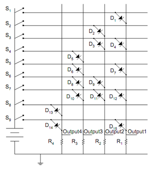
Figure: A Diode ROM Matrix