Electromagnetic deflection
Early experimenters with electricity and magnetism noticed that the electric current produces a magnetic field. This discovery was an accident, but it was an accident that, given the curiosity of scientist, was bound to occur. When a magnetic compass is placed near the wire carrying a direct electric current, the compass does not point toward magnetic north. The needle gets displaced. The extent of the error relies on the fact on how close the compass is brought to wire, and on how much current the wire is carrying.
Scientific experimenters are just like children, they like to play around with things. Most likely, when this effect was 1st observed, the scientist tried different arrangements to see how the compass needle could be displaced, and how small a current could be detected. An attempt was made to obtain the greatest possible current-detecting sensitivity. Wrapping the wire in the coil around compass results in a device which would indicate a tiny electric current. This effect is termed as galvanism, and the meter so devised was called a galvanometer.
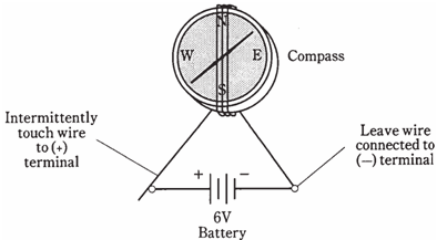
Figure-- A simple galvanometer. The compass must lie flat.
Aha-a device for measuring current! Then, the challenge was to standardize the galvanometer somehow, and to set up some standard so that the universal meter could be engineered.
You can easily make galvanometer of your own. Just buy a compass, about 2 feet of insulated bell wire, and a 6-volt lantern battery. Set it up as shown in the Figure given. Wrap the wire around the compass 4 or 5 times, and align the compass so that the needle point's right along the wire turns while the wire is disconnected from battery. Connect 1 end of the wire to the minus terminal of the battery. Touch other end to the plus terminal, intermittently, and watch the compass needle. Do not leave the wire connected to the battery for any time unless you want to drain battery in a hurry.
You can buy a resistor and the potentiometer at a place like Radio Shack, and set up an experiment whichy shows how galvanometers measure current. For a 6-V lantern battery, the fixed resistor should have a value minimum of 330 Ω at 1/4 watt, and potentiometer should have the value of 10 KΩ (10,000 Ω) maximum. Connect resistor and potentiometer in series between 1 end of the bell wire and 1 terminal of the battery, as shown in the Figure given below. The center contact of potentiometer should be short-circuited to 1 of the end contacts, and the resulting 2 terminals used in circuit. When we adjust potentiometer, the compass needle should deflect less or more, depending upon the current by the wire.
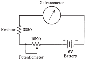
Figure: Circuit for demonstrating how a galvanometer indicates relative current.