Common-source circuit
There are 3 different circuit hookups for FETs, as there are for bipolar transistors. These 3 arrangements have source, gate, or drain at the signal ground.
The common-source circuit places source at the signal ground. The input is at the base. The general configuration is shown in the figure given below. An N-channel JFET is used here,but device could be an N-channel, depletion-mode MOSFET and circuit diagram would be same. For an N-channel, enhancement-mode device, an extra resistor would be essential, running from the gate to the positive power supply terminal. For P-channel devices, the supply would give a negative, instead of a positive, voltage.
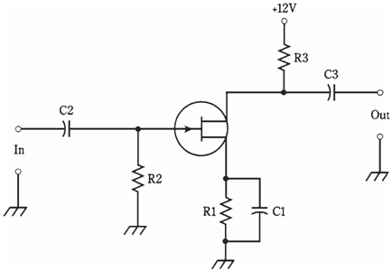
Figure--Common-source circuit configuration.
This circuit is an exact replica of grounded emitter bipolar arrangement. The only difference is lack of a voltage dividing network for the bias on the control electrode.
Capacitor C1 and resistor R1 place source at the signal ground while elevating this electrode above ground for direct current. The alternating current signal enters through C2; resistor R2 adjusts input impedance and gives bias for the gate. The alternating current signal passes out of circuit through C3. Resistor R3 keeps output signal from being shorted out through power supply.The circuit of figure is the basis for amplifiers and oscillators, especially at radio frequencies. The common source arrangement gives the greatest gain of 3 FET circuit configurations. The output is 180 °out of phase with input.