Radio-frequency power amplifiers
The common application of vacuum tubes in the modern technology is in RF amplifiers, especially at high frequencies and power levels of more than 1kW. The two configurations are employed: grounded cathode and grounded grid.
Grounded cathode
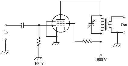
A simplified schematic diagram of a grounded-cathode RF power amplifier, by using a pentode tube, is shown in the figure given below. The output circuit is tuned to the operating frequency. The circuit is operated in any of these class-AB, B, or C. If the amplifier is linear, class C cannot be used at all.
The input impedance of the grounded-cathode power amplifier is moderate; the plate impedance is quite high. Impedance matching between amplifier and load (commonly an antenna) can be obtained by tapping the coil of the output tuned circuit, or by using a transformer. In example of the figure given below, transformer output coupling is used.
Grounded grid
Grounded-cathode RF power amplifiers can oscillate, unless they are neutralized or given with some negative feedback. The oscillation occurs at some frequency far removed from the operating frequency. Generally known as parasitic oscillation, it can rob the amplifier of output power at the desired frequency, and causing interference to communications on frequency or frequencies of the oscillation. Neutralization can be a very tricky business. When the tube can be replaced, the neutralizing circuit should be readjusted. The adjustment is critical rather. The improved stability, without the requirement of neutralization, can be obtained by grounding grid, instead of the cathode, of the tube in the RF power amplifier.
The grounded-grid configuration requires more driving power than the grounded- cathode scheme. While a grounded-cathode amplifier might produce 1 kW of RF output for 10 W input, a grounded-grid amplifier needs about 50 W to 100 W of driving power to produce 1 kW of RF output.
A simple grounded grid RF power amplifier is shown in the figure given below. The cathode input impedance is low, and plate output impedance is high. The output impedance can be matched by same means as with the grounded cathode arrangement. In the figure given below, a transformer can be used between the plate circuit and the load.
Plate voltages in circuits of the given figure are given only as examples. The amplifiers shown would produce 75 W to 150 W of RF power output. An amplifier with 1 kW of RF output would have the plate voltage of 2 to 5 kV, depending on tube characteristics and class of amplifier operation.
The characteristic grounded grid linear amplifiers are operated in class-AB or B. If linearity is not significant (as in CW, FSK, or FM operation), then class-C gives improved efficiency, although driving power requirement increases, such that 100 W or even 200 W of RF input is necessary to get 1 kW of RF output.
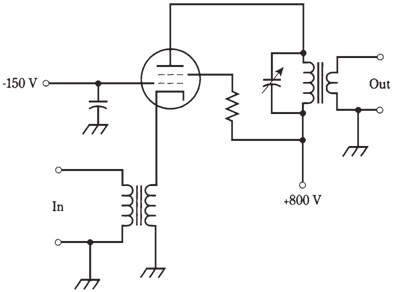
Figure--A grounded-grid RF power amplifier.