Frequency multiplication:
When the current passes through a diode, half of the cycle is cut off, as shown in the Figure given below. This happens no matter what the frequency, from 60-Hz utility current by RF, as long as the diode capacitance is not too large.
The output wave from diode looks much different than input wave. This condition is termed as nonlinearity. Whenever there is nonlinearity of any kind in the circuit-that is, whenever output waveform is shaped differently from input wave- form-there will be harmonic frequencies in output. These are waves at integer multiples of input frequency. Nonlinearity is undesirable many times. Then engineers strive to make circuit linear, such that the output waveform has exactly same shape as input waveform. But sometimes a circuit is required which will produce harmonics. Then nonlinearity can be introduced deliberately. Diodes are kept ideal for this.
A basic frequency multiplier circuit is shown in the Figure given below. The output LC circuit is tuned to desired nth harmonic frequency, nfo, instead of the input or fundamental frequency, fo.
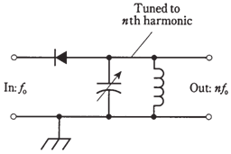
Figure-- A frequency multiplier circuit.
For the diode to work as a frequency multiplier, it should be of a type which would also work well as a detector at same frequencies. It means that the component should behave like a rectifier, but not like a capacitor.