Amplitude limiting:
The forward breakover voltage of the germanium diode is around 0.3 V; for a silicon diode it is around 0.6 V. The diode will not conduct until the forward bias voltage is at least as great as forward breakover voltage. The flip side
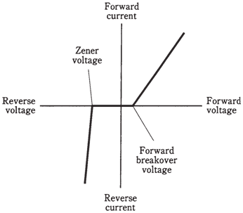
Figure- Current through a Zener diode, as a function of bias voltage.
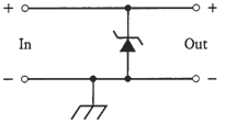
Figure- Connection of Zener diode for voltage regulation.
is that the diode will conduct when the forward bias exceeds breakover value. In this case, voltage across diode will be constant: 0.3 V for germanium and 0.6 V for silicon.
This property is used to advantage when it is required to limit amplitude of a signal, as shown in the Figure given below. By connecting 2 identical diodes back to back in parallel with signal path (A), the maximum peak amplitude is restricted, or clipped, to forward breakover voltage of diodes. The input and output waveforms of the clipped signal are shown at B. This scheme is used in radio receivers sometimes to prevent blasting when the strong signal comes in.
The downside of diode limiter circuit is that it introduces distortion when limiting takes place. This may not be a problem for the reception of Morse code, or for signals which rarely reach the limiting voltage. But for the voice signals with amplitude peaks which rise well past the limiting voltage, it can degrade seriously the audio quality, even rendering the words indecipherable.
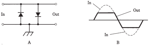
Figure-- At point A, two diodes can work as a limiter. At point B, the peaks are cut off by the action of diodes.