Design of Slideways
Slideways are designed for wear resistance and stiffness.
Design of Slideways for Wear Resistance
The wear resistance of slideways is principally dependent upon maximum pressure acting upon the mating surfaces. This condition may be described as
Equation 1
pmax ≤ Pmp
In which
pm stands for maximum pressure acting on the mating surface, and
pmp stands for permissible value of the maximum pressure.
It is seen during the consequent analysis that slide-way designed for maximum pressure is quite complicated. Occasionally, this design is replaced by a simple procedure based on the average pressure acting upon the mating surfaces. The condition is that:
Equation 2
Pa ≤ Pap
In which
pa stands for average pressure acting on the mating surface, and
pap stands for permissible value of the average pressure.
Therefore from Equation (1) and (2), the design of slideways for wear resistance requires that
(1) pm and pa to be known,
(2) pmp and pap to be known, and
(3) The values of pmp and pap are given for dissimilar operating conditions of slideways on the basis of experience. For ascertaining pm and pa, the first and foremost task is to determine the forces acting on the mating surfaces. Forces acting upon the mating surfaces in combination of V and flat slideways.
The combination of V and flat slideways is generally utilized in lathe machines. The schematic figure of slideways and the forces acting upon the system for the case of orthogonal cutting are demonstrated in diagram.
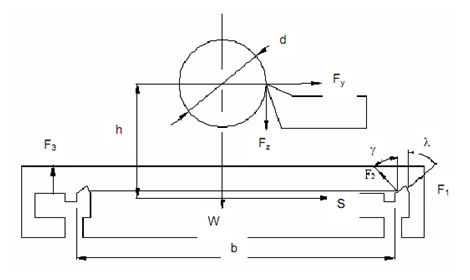
Figure: Forces Acting on Combination of V and Flat Sideways
The forces acting on V and flat slideways are :
(1) Cutting force component Fz that is in the direction of the velocity vector and Fy that is radial,
(2) Weight of carriage W, and
(3) Not known forces F1, F2 and F3 acting on the mating surfaces. The unknown forces are computed from following equilibrium conditions:
Sum of components of forces acting along Y-axis = 0
i.e.
Equation 3
∑ Y = 0
F1 sin λ - F2 sin ϒ + Fy = 0
Sum of components of forces acting along Z-axis = 0
i.e.
Equation 4
∑ Z = 0
F1 cos λ + F2 cos ϒ+ F3 - W - Fz = 0
Moment of all forces about X-axis = 0
i.e.
Equation 5
∑ Mx = 0
(F1 cos λ. b/2) + (F2 cos ϒ. b/2) - (Fz . d/2 ) - ( Fy . h) - (F3. b/2) = 0
F3 = (F1 cos λ) + (F2 cos ϒ) - (Fz (d/b)) - (Fy (2h/b))
Substituting value of F3 in Eq. (4), we get,
Equation 6
(F1 cos λ) + (F2 cos ϒ) - (F1 cos λ) - (F2 cos ϒ) - (FZ (d/b)) - (FY (2h / b)) - FZ -W = 0
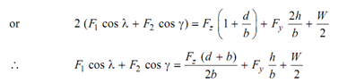
If the apex angle of the V is 90°, and suppose that present angle γ may change to γ = 90 - λ, the solution of simultaneous algebraic Eqs. No. (3) and (6) gives :
Equation 7:
F1 = [(FZ (d+b) / (2b)) cos λ] + [Fy (h/b) cos λ] - [Fy sin λ + (W/2) cos λ]
Equation 8:
F2 = [(FZ (d+b) / (2b)) sin λ] + [Fy (h/b) sin λ] - [Fy cos λ + (W/2) sin λ]
Substituting the values of F1 and F2 in Eq. (5) we get,
Equation 10:
F3 = [(FZ (b+d) / (2b))] + [Fy (h/b) + (W/2)]
Eq. (10) illustrates the forces acting upon the mating surfaces in combination of two flat sideways.
The schematic figure of the slideways and the forces acting on the system under orthogonal cutting conditions are displayed below.
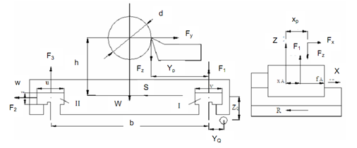
Figure: Forces Acting on Combination of Two Flat Slideways
The forces that are acting upon combination of two flat slide-ways are:
(1) Cutting force components, that are axial Fx, radial Fy, and Fz in the direction of velocity vector.
(2) Weight of carriage, W.
(3) Unknown forces F1, F2 and F3 acting on the mating surfaces.
(4) Frictional forces μF1, μF2, μF3, in which μ is the coefficient of friction between the sliding surfaces.
The unknown forces F1, F2 and F3 are calculated from subsequent equilibrium conditions :
Equation 10
∑ X = 0
Fx + μ (F1 + F2 + F3) - R = 0
Equation 11
∑ y = 0
F2 - Fy = 0
F2 = Fy
Equation 12
∑ z = 0
F1 + F3 - Fz - W = 0
Equation 13:
∑ Mx = 0
W (b/2) + FZ yP - Fy h - F3b = 0
From Eq (13)
F3 = ((Fzyp - Fyh) / b)) + W/2
On substituting the value of F3 in Eq. (12)
Equation 14
F1 = Fz + W/2 - ((Fzyp-Fyh) / b))
The pulling force, R is calculated from Eq. (10) on substituting the values of F1, F2 and F3.
Equation 15
R = Fx +μ (Fz + Fy + W )