Symbols for logic gates
A logic gate is an electronic switch which performs a logic operation. The earliest logic gates were built by using vacuum tubes; later, transistors and diodes were used. Modern logic gates are fabricated on ICs, having hundreds or even thousands of gates per chip.An inverter (NOT gate) has an input and an output. Other logic gates have 2 inputs and a single output usually. The symbols for various logic gates are shown in the figure given below.
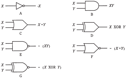
Figure--Symbols for logic gates: NOT (A), AND ( ), OR (C), XOR (D), NAND (E), NOR (F), and XNOR (G).
It is possible for NAND, AND, OR, or NOR gates to have 3 or more inputs. For an AND gate, output is high if all of the inputs are high. For an OR gate, the output is low if all the inputs are low. The multiple-input NAND and NOR gates perform conjunction or disjunction operation 1st, followed by negation. The figure given below shows schematic symbols for 4-input AND 4-input NOR gates.
The XOR and XNOR operations are difficult to define when there are 3 or more inputs. These fall in the category of complex logic operation.