Logic signals
On a single wire or line, a binary digital signal is full-on or full-off at any given moment. These are logic high and low, and are represented by direct current voltages. The high voltage is approximately +3 V to +5 V, and the low voltage is in between 0 V and +2 V.
Parallel data transfer
A binary number has many binary digits, or bits. The number of bits relies on how big the numbers can get. For instance, if you want to send binary numbers from 0000 to 1111 (which corresponds to decimal numbers 0 through 15), you require four bits. If you want to transmit numbers as high as 11111111, or decimal 0 to 255, you require eight bits. For the large decimal numbers, you will require many bits—at times several dozen.
The bits can be sent along the separate wires or lines. When this is done, number of lines corresponds to number of bits in binary number. That is, in order to send the binary numbers up to 1111, you require four lines; to send numbers up to 11111111, you require eight lines. This is called as parallel data transfer, as the bits are sent along lines that are effectively in parallel to each other. Clearly, parallel data transfer has restrictions. For large numbers, it would require many lines. This can present certain logistic problems, for instance in long distance radio or wire transmission.
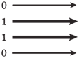
Figure-- Parallel data transfer of the binary number 0110
Serial data transfer
In the radio communications by using parallel data transfer, each line should correspond to a different frequency; the result is that large binary numbers require many channels. This translates into a broad signal bandwidth. The required bandwidth is not always easy to obtain. It is especially difficult at low and shortwave frequencies, where wideband signals present not only an engineering hassle, but tend to hog the spectrum space.
Fortunately, there is other way to send binary data, and this method requires only one line or radio frequency. It is called as serial data transfer. Rather than sending each bit on a separate line, the bits are transmitted one after other in defined sequence.To send binary numbers up to 1111 serially, you require four time slots. For the serial transmission of binary numbers up to 11111111, you require eight slots. Each slot has a fixed duration. Generally, all slots are of equal length. A 4-bit serial signal is shown in the figure given below.
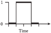
Figure--Serial representation of binary number 0110.
Assume that the duration of a bit is 1 ms.. The bit rate is then 1,000 bits per second (bps). Generally if the bit duration in seconds is t, then bps rate is 1/t. Radio data communications systems operate at speeds upwards of 10,000 bps, or 10 kbps.Serial data transfer is slower than parallel transfer. This is the essential tradeoff for the convenience of the single transmission line, or for narrower radio-signal bandwidth. In electronics, you never get something for nothing.
Positive versus negative logic
Usually, logic 1 is high and logic 0 is low. This is known as positive logic. But these states can be reversed, and the results will be just as good. When logic 1 is low and logic 0 is high (so that a bit 1 is “off” and a bit 0 is “on”), negative logic is being used.In the rest of this chapter, positive logic is the rule. This is simply to minimize con- fusion.