Voltage-Controlled Current Sources:
Consider the circuit illustrated in Figure (a). By judicious redrawing it may be rearranged as in Figure (b) where it is simple to recognize an NIC terminated into R realizing a -R at input port of NIC. As a result, we obtain the equivalent circuit of Figure (c). Analysis of this equivalent circuit gives
I out = VL /- R + (VL - Vm ) / R = - Vm /R
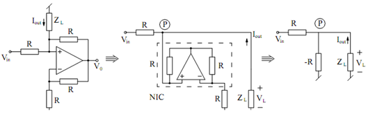
(a) (b) (c)
Figure: Realization of Voltage-controlled Current Sources
Therefore, the circuit of Figure (a) is an inverting VCCS.
A slightly different arrangement giving a non-inverting VCCS is illustrated in Figure (a).
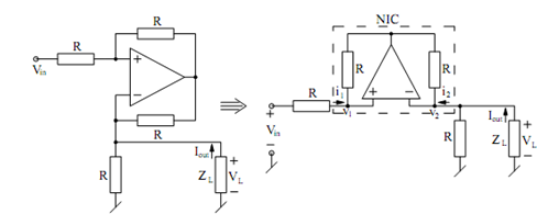
(a) (b)
Figure: A Non-inverting VCCS using an Op-amp
With some re-arrangement the circuit may be redrawn as in Figure (b) where once again, we may identify an NIC. For the NIC, we have
V1 = V2 = VL
also as the two resistors around the NIC are identical, we have i1 = i2. But
i = (Vm - V1 ) /R and i2 = Iout - (V2 /R) = iout - V1/R . From these equations, it follows that
(Vm - V1 )/R = iout - V1 /R which leads to
Iout =+ Vm /R