Series and Parallel Resonance:
Resonance is that condition in any AC circuit at a specific frequency, while the applied voltage and resultant current are in same phase. Thus, at resonance the power factor of the AC circuit is unity and it acts like a pure resistive circuit.
Series Resonance
In series RLC circuit at a specific frequency when inductive reactance (XL = ωL) becomes equal to the capacitive reactance ( X C = 1/ ωC ), then the circuit is said to be at resonance
XL = XC
In the series RLC circuit of Figure, the circuit current I is specified by
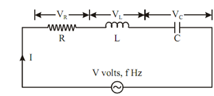
Figure: Series Resonance Circuit
I =( V/ Z) A
where Z represents the equivalent impedance of the circuit.
Z = R + j ωL +(1/ j ωC)
= R + j ωL -(1/ ωC)j
Z = R + j ( X L - X C )
where
X L = ωL and XC = 1/ ωC
= R + jX
where (XL - XC) = X (Net Reactance)
Therefore
I = V / (R + j ( X L - X C )) = V / R + jX Amp
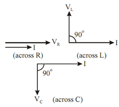
Figure: Voltage and Current Phasor
And voltage drop across resistance, R is VR = IR (in phase with I)
Voltage drop across inductance, L is VL = I XL (leading I by 90o)
Voltage drop across capacitance, C is VC = I XC (leading I by 90o)
The phasor diagram of the variables of the entire circuit is shown in Figure
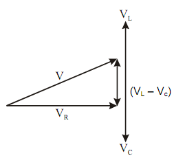
Figure: Voltage Vector Diagram of RLC Series Circuit