Resistive, Inductive and Capacitive Circuits:
AC through Pure Resistive Circuit
Applied voltage, v = Vm sin ωt
The resultant current, i
i = V/ R = (V m / R )sin ωt = Im sin ωt
Current, i is in phase with applied voltage, v. The waveforms and phasor diagram are illustrated in Figures (a)and (b), respectively.
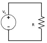
Figure: Resistive Circuit
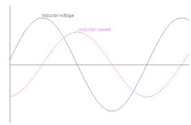
Figure: Current and Voltage Waveforms
AC through Pure Inductive Circuit
The circuit is illustrated in Figure. Again the applied voltage is given by
v = Vm sin ωt
v = L (di /dt)
Now,
v = Vm sin ωt
∴ Vm sin ωt = L ( dt/ di)
∴ di = (Vm / L ) sin ωt dt
Integrating both sides, we get
i = Vm / L ∫sin ωt dt
= Vm/ ωL (- cos ωt) = - (Vm/ ωL) cos ωt
= (Vm /ωL) sin (ωt - (π/2))
= (Vm/ X L) sin ( ωt -( π /2))
where XL = inductive reactance = ωL in ohm, if we put Vm / X L = Im , then
i = I msin ( ωt - (π /2))