Internet Client Control Task
A distributed system is to be implemented using networked PCs.
The role of the system in this task is to implement an environmental control system which is remotely supervised by a client utility that you will write the code for.
An environmental controller is attached to a PC which acts as an Internet server. The controller, when enabled, turns a heater on or off depending on the temperature and reports to the server. The client sends messages to the server, the server communicates with the controller and replies to the client if necessary. The message protocol used is defined in section 2.
1.1 Client commands to the server - you will have to design a GUI and write client code to implement this
- reset controller
- enable / disable the controller
- set the temperature Set Point of the controller i.e. the desired temperature range = 0 to 250C
- request the controller's status
- request the controller's set point
- request current temperature
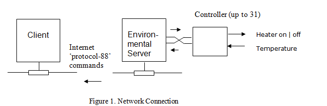
1.2 Starting Point
A simple client program is available ClientV1 including source code.
The server code is available as ServerV1.exe (executable only).
Unzip the server code, compile and run ClientV1.sln and run ServerV1 on a single PC.
ServerV1 - Put Server in listening mode (Click Listen)
ClientV1 - Connect to server 'local host'
Send commands from the Client to the Server by typing the Protocol commands into the text box and pressing return. Observe the response. Example commands are in the protocol section below.
Simulated Slave Controller
The server code simulates the slave controller and no hardware needs to be attached. The server code provides a random simulated temperature and compares this with the Set Point and the Status before deciding to turn the heater on or off.
1.3 Suggested Development Areas
- Implement the Reset message (this sets the controller to a known state)
- Implement enable / disable controller
- Implement the set Set Point message
- Implement the request Status, Set Point and Temperature responses
- Implement a Mimic (display) Panel on the Client GUI to give a user feedback about the condition of the real controller
- Display the data from the controller graphically
- Log the Actions of the Client and Slave
- Add a database feature ( time, status, temperature etc)
- Automate - use time of day info to enable and disable slave
- Allow contact with additional slave controllers 2-31 via address field
- Implement error messages and Protocol code.
- Provide Hints, Help and Version ID information as appropriate
- Develop unit based code
2. PROTOCOL-88. Character Based Serial Protocol - N.b. You will NOT find this on the web.
- Messages form a simple communication link between computers.
- The protocol-88 message format is based on ASCII characters.
- The message format is 14 characters in length including the framing characters
- The message is framed by the characters '<' and '>'
- The message consists of 6 internal fields defined as:
key: [t] = tens [u] = units
|
(a) slave address [t][u]
|
(d) data [t][u]
|
|
(b) command [t][u]
|
(e) spare e.g. additional data
|
|
(c) type [t][u]
|
(f) error correction e.g. checksum
|
thus any field may take on values of tens and units [t][u] i.e. 00 to 99
A typical message is thus:
<010203040599>
01 = slave address (1), 02 = command (2), 03 = command type (3), 04 = data (4), 05 = spare (5), 99 = error bits (99).
Links to the Client and the Server executables are at: www.det.mmu.ac.uk/staff/allwork/
They are Client1.zip and ServerV1.exe
A typical message:
|
<
|
Address
|
com-mand
|
type
|
data
|
spare
|
error
|
>
|
|
|
[t]
|
[u]
|
[t]
|
[u]
|
[t]
|
[u]
|
[t]
|
[u]
|
?
|
?
|
?
|
?
|
|
|
1
|
2
|
3
|
4
|
5
|
6
|
7
|
8
|
9
|
10
|
11
|
12
|
13
|
14
|
Definition of message fields:-
|
command
|
type ( of command )
|
data
|
|
00 (reset)
|
none
|
none
|
|
01 (set client-to-server)
|
01 (enable - on / off)
|
[1]= on | [0]= off
|
|
|
02 (set_point)
|
[t][u]
|
|
|
03 (not applicable)
|
|
|
02 (request & response)
client-to-server & server-to-client)
|
01 (local_status_enable)
|
[1]= √ | [0]= x
|
|
|
02 (set_point)
|
[t][u]
|
|
|
03 (temperature)
|
[t][u]
|
√=enabled x =disabled
EXAMPLES:
- Error detection is NOT incorporated into these examples (nor by my server code)
- unused fields are indicated as X - by default these should be set to 0
- address 00 is the master
a) a message from the client to slave_1 indicating a local reset would be: < 0 1 0 0 0 0 0 0 0 0 0 0 >
(b) a message from the client to slave_2 issuing the command set controller status to enabled would be:
< 0 2 0 1 0 1 0 1 0 0 0 0 >
(c) a message from the client to slave_1 issuing the command set the set_point to 24 would be:
< 0 1 0 1 0 2 2 4 0 0 0 0 >
(d) a message from the client to slave_1 issuing the command request the temperature would be:
< 0 1 0 2 0 3 0 0 0 0 0 0 >
if the slave temperature is currently 18 the reply from the server would be: < 0 1 0 2 0 3 1 8 0 0 0 0 >
You might like to try typing the following into the client:
<010101010000> - set enabled true - enable slave 1 (the server) - enabled 'LED' should turn red.
<010201000000> - request status: enabled - reply should be <010201010000>
<010102150000> - set the temperature set point to 15 degrees - heater should come on and off as temperature varies above and below 15 degrees.
<010203000000> - request temperature the reply should be <010203TU000> where TU is temperature.