There are various computational models for representing the parallel computers. In this part, we discuss various models. These models would give a platform for the designing as well as the analysis of the parallel algorithms.
Combinational Circuits
Combinational Circuit is one of the forms for parallel computers. In interconnection networks, many processors communicate with each other directly and do not need a shared memory in between. Mostly, combinational circuit (cc) is a connected arrangement of logic gates with a set of m input lines and a set of n output lines as given in Figure. The combinational circuits are mostly made up of various interconnected components arranged in the form called as stages as given in Figure.
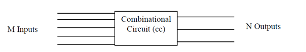
Combinational circuit
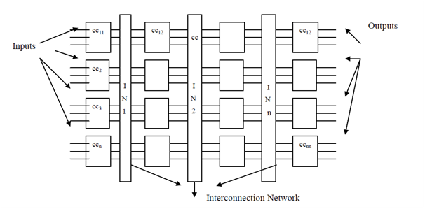
Detailed combinational circuit
It might be noted here that there is no feedback control employed in combinational circuits. There are a small number of terminologies followed in the context of combinational circuits such as fan in and fan out. Fan in indicates the number of input lines attached to each device and fan out indicates the number of output lines. In Figure , the fan in is 3 and fan out is also 3. The following parameters are used for analyzing a combinational circuit:
1) Depth: It means that the total number of phases used in the combinational circuit starting from the input lines to the output lines. For example, in the depth are 4, as there are four different phases attached to a interconnection network. The other form of interpretation of depth can be that it represents the worst case time complexity of resolving a problem as input is given at the initial input lines and data is transmitted between various phases through the interconnection network and at the end reaches the output lines.
2) Width: It represents the total number of devices attached for a particular phase. For example in Figure, there are 4 components linked to the interconnection network. It means that the width is 4.
3) Size: It represents the total count of devices used in the complete combinational circuit. For example, in Figure , the size of combinational circuit is 16 i.e. (width * depth).