1. The size of the multiplexer used to implement a truth table can be cut in half (e.g. 4 inputs instead of 8) if one of the variables is used as an input instead of being connected to a select line. For example, a truth table with inputs A, B, C, could be implemented using a 4-input multiplexer with A and B connected to the 2 select lines. A and B would then be able to select 0, 1, C or C (assuming that an inverter is available for C). Figure out how to re-implement Question 3 this way and prove that your solution is correct with a LogicWorks simulation.
2. Another way to implement a truth table is to use a multiplexer. A 2 to1 mux, like the one discussed in class, can select one of two inputs using a single control input. A 4 to 1 mux selects one of four inputs using two control inputs. Consider the following. By using the 2 control inputs as the table input variables and appropriately hard wiring the 4 inputs of the mux to 0 or 1, a 2 input truth table can be implemented.
Using this approach, an n input truth table can be implemented using a 2n to 1 mux.
a) Design a 2 to 1 multiplexer. Verify its operation using LogicWorks.
b) Now using the 2-way routing switch as a building block (use the device editor in LogicWorks to encapsulate the 2-way switch), design a multiplexer large enough to implement the truth table described in Question 2 (Z3 only). Predict the propagation delay, Tpd, of your multiplexer (you will need this to figure out how to space the inputs to your circuit in time). Test your multiplexer with appropriate waveforms and verify that the measured Tpd is consistent with its predicted value.
c) Hard wire the inputs to your multiplexer to implement the truth table described in Question 2(Z3). Verify its operation using LogicWorks.
d) Explain the presence of any anomalous signals (glitches) in your output and give an example of an input transition those results in a glitch at the output. Show this example using LogicWorks.
3. At night, a security guard is suppose to walk from room to room in a building having four rooms. Create a motion detector circuit which will detect the following conditions:
1.- Exactly one motion sensor being equal to 1, meaning, motion has been detected in one room.
2.- No motion sensor is equal to 1, meaning, the guard is either sitting or sleeping and no intruder is present in the building.
3.- Two or more sensors are equal to 1, meaning, there must be an intruder or intruders in the building.
The circuit to be designed has four inputs, S1,S2, S3, S4, one input per sensor, and three outputs, Z1, Z2, Z3, corresponding, respectively, to each one of the mentioned three conditions. Each output is set to 1 when the corresponding condition occurs; otherwise, it is set to 0.
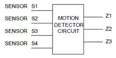
The following block diagram represents the circuit to be designed.
a) Produce the truth table of the three output functions.
b) Determine the minimal ΣΠ and ΠΣ for Z3.
c) Implement the corresponding circuit for Z3 using NAND-NAND and NORNOR logic in LogicWorks. Show that your circuits implement the specified truth tables.
d) Using the LogicWorks PROM/PLA wizard, generate the look-up table corresponding to the truth table and generate a test circuit. Verify its operation using LogicWorks.