Reference no: EM131277254
Lab Assignment
• Diode Circuits--Half-Wave and Full-Wave Rectifier lab assignment
Introduction:
Week 2 lab is based on half-wave and full-wave rectifiers. Rectifiers are widely used in power supplies to provide the required DC voltage.
Please review the following videos before getting started with this lab:
1. Watch the video: "Video 3: Basic Electrical Components"
https://content.grantham.edu/at/EE212/1-20-2015/week2/Fundamental_of_Breadboard.mp4
2. Watch the video: "Video 4: Fundamentals of breadboard"
https://content.grantham.edu/at/EE212/1-20-2015/week2/Basic_Electrical_Components.mp4
3. Watch the video: "Video 5: Simple resistive circuit with NI myDAQ"
https://content.grantham.edu/at/EE212/1-20-2015/week2/Simple_Resistive_Circuit_with_NI_myDAQ.mp4
Materials and Equipment:
Materials:
• Simulated Parts (Multisim):
o 10:1 center-tapped transformer
o Two diodes 1N4001
o Two 2.2 kΩ resistors
o One 100 μF, 50 V electrolytic capacitor
o One fuse (any rating is fine since it is for simulation only)
• Hardware Parts (In the Toolbox):
o Two diodes 1N4001
o Two 2.2 kΩ resistors
o One 100 μF, 50 V electrolytic capacitor
Equipment:
• Virtual Instruments (Multisim):
o Function Generator (Multisim)
o Function Generator (NI Elvisms Instrument Launcher)
o Arbitrary Waveform Generator (NI Elvismx Instrument Launcher)
o Tektronix oscilloscope (Multisim)
o Oscilloscope (NI Elvismx Instrument Launcher)
• Hardware Equipment:
o Breadboard
o NI myDAQ Instrument Device
o Screw Driver
o Screw Terminal connector
o Jumper wires
o Oscilloscope and Function generator from NI ELVISmxIntrument Launcher
Procedure:
***** This lab has to be implemented in both software (running simulations on Multisim) and hardware (using NI myDAQ) *****
Part A: Half wave rectification:
Software (Multisim):
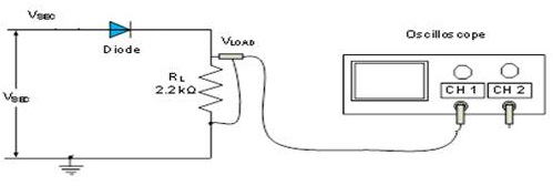
8. Construct the circuit of a half-wave rectifier in Figure 1 in Multisim. Use a function generator to provide the AC input of 30VRMS (Make sure to convert the RMS to Peak voltage) and use a center tapped transformer to obtain VSEC . With a 10:1 ratio, the VSEC should be 3 VRMS. Be sure to set the tolerance of the resistor to 20%.
9. Connect the Tektronix oscilloscope so that channel 1 is across the secondary output side of the transformer and channel 2 is across the load resistor (RL). Observe the waveforms VSEC and VLOAD.
10. The output isn't very useful as a DC source because of the variations in the output waveform. In order to produce steady DC from a rectified AC output, you need to add a filter. There will be an AC ripple voltage component at the power supply frequency for a half-wave rectifier, twice that for full-wave, where the voltage is not completely smoothed. Connect a 100 μF capacitor (C1) in parallel with the load resistor (RL). (Note the polarity of the capacitor).
11. Measure and plot the peak-to-peak ripple voltage, V8RIPPLE, of the output. Measure the ripple frequency. Tabulate all data gathered and compare the results with and without the filter capacitor.

Figure 1
Hardware (NI myDAQ):
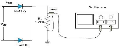
12. Using the voltage VSEC obtained from the simulation, build the circuit in Figure 2 on the breadboard with VSEC as an input, which connects to the diode and load resistor RL in series. (See Figure 3)
13. Using the jumper wires, screw driver, and screw terminal connector, connect the board to NI MyDAQ Instrument Device to analyze the circuit.
14. Use channel AO0 on the NI myDAQ Instrument Device to provide the input (VSEC) and channel AI0 to measure the output voltage(VLOAD).
15. Using the function generator from NI ELVISmx Instrument Launcher, provide the input voltage VSEC to the circuit. Measure the output voltage VLOAD, across the load RL using the oscilloscope.
16. In order to produce steady DC from a recitified AC output, you need to add a filter. Connect a 100 μF capacitor (C1) in parallel with the load resistor (RL) (Note the polarity of the capacitor)
17. Measure and plot the peak-to-peak ripple voltage, VRIPPLE, of the output. Measure the ripple frequency. Tabulate all data gathered and compare the results with and without the filter capacitor.

Figure 2
Review questions:
18. What is the purpose of having a half-wave rectifier in the circuit?
19. Describe the procedure in this lab to arrive at the final design of both the hardware portion and the software portion to achieve the design objectives?
20. Discuss the impact of having the capacitor on the output voltage and the effect of additional load on the ripple voltage.
Deliverables:
21. Measured voltage VSEC, the output peak voltage, VLOAD and ripple voltage VRIPPLE. Capture screenshots of your measurements from Multisim.
22. Place your student ID card on the breadboard and take a picture of the circuit board and pin out on the NI myDAQ device.
23. Take screenshots of the measurements obtained from function generator and oscilloscope on the NI ELVISmx Instrument Launcher on your screen.
Part B: Full wave rectification:
Software (Multisim):
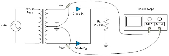
24. Construct the circuit of a half-wave rectifier in Figure 3 in Multisim. Use a function generator to provide the AC input of 30VRMS (Make sure to convert the RMS to Peak voltage) and use a center tapped transformer to obtain VSEC . Notice that the ground for the circuit has changed. With a 10:1 ratio, the VSEC should be 3 VRMS. Be sure to set the tolerance of the resistor to 20%.
25. Connect the Tektronix oscilloscope so that each channel is across each diode. Observe the waveforms VSEC across each diode and notice that they are out of phase with each other. You can use the third channel to observe the output voltage VLOAD across the resistor.
26. In order to produce steady DC from a rectified AC output, you need to add a filter. Connect a 100 μF capacitor (C1) in parallel with the load resistor (RL). (Note the polarity of the capacitor).
27. Measure the peak-to-peak ripple voltage, VRIPPLE, of the output. Measure the ripple frequency. Tabulate all data gathered and compare the results with and without the filter capacitor.

Figure 3
Hardware (NI myDAQ):
28. Due to the lack of accessibility with NI myDAQ device, it is not possible to use the function generator to provide the two inputs simultaneously using the hardware. Therefore, you will be using the "Arbitrary Waveform Generator" for this part.
29. Using the jumper wires, screw driver and screw terminal connector, connect the board to NI MyDAQ Instrument Device to analyze the circuit.
30. Please use the attached two sine waveforms (Fullwave Input 1 and Fullwave Input 2) that has the same amplitude as the 3 VRMS and are 180 out of phase with each other to provide input voltages VSEC1 and VSEC2 as two inputs to the two diodes for full wave rectification.
31. Using the jumper wires, screw driver and screw terminal connector, connect the board to NI MyDAQ Instrument Device to analyze the circuit.
32. Using the Arbitrary Waveform Generator from NI Elvismx Instrument Launcher, load the two files provided in step 6 for output channel AO0 and AO1. Launch the Oscilloscope (Set the Time/Div to 20ms) and run to measure the output voltage VLOAD, across the load resistor RL. Use channel AI0 to plot the output waveform for VLOAD.
33. In order to produce steady DC from a rectified AC output, you need to add a filter. Connect a 100 μF capacitor (C1) in parallel with the load resistor (RL). (Note the polarity of the capacitor).
34. Measure and plot the peak-to-peak ripple voltage, VRIPPLE, of the output. Measure the ripple frequency. Tabulate all data gathered and compare the results with and without the filter capacitor.

Figure 4
Review questions:
35. What is the purpose of having a full-wave rectifier in the circuit?
36. Describe the procedure in this lab to arrive at the final design of both the hardware portion and the software portion to achieve the design objectives?
37. Discuss the impact of having the capacitor on the output voltage and the effect of additional load on the ripple voltage.
38. How is the output of the full-wave rectifier different from half-wave rectifier?
Deliverables:
39. Measured voltage VSEC1 and VSEC2, the output peak voltage
40. Using two files provided for the input VSEC1 and VSEC2, measure the load voltage VLOAD and ripple voltage VRIPPLE. Capture screenshots of your measurements from Multisim.
41. Place your student ID card on the breadboard and take a picture of the circuit board and pin out on the NI myDAQ device.
42. Capture screenshots of your measurements from the NI ELVISmx Instrument Launcher showing both the input from the function generator and output on the oscilloscope on your screen.
Lab Report:
• Use the Lab report template found in the "Tools and Template" link in the navigation center.
• Include all the deliverables from Part A and Part B.
• Include all the screenshots of the measurements from Multisim, circuit design on the breadboard using NI myDAQ device and measurements from MI ELVISmx Instrument Launcher.