Reference no: EM132205262
Assignment Questions -
Q1. For circuit in the fig.1
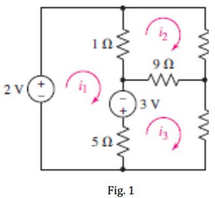
a. Label all the node voltages and show and label all branch currents for mesh analysis if they are not already labelled.
b. Calculate the node voltages and all branch currents. Show your equations and solutions in a logical order.
c. Calculate the power generated or absorbed by each element including the sources. Show that power is conserved in the circuit.
Q2. Consider the circuit in Fig. 2.
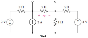
a. Write and solve mesh equations.
b. Determine the Thevenin equivalent of the circuit shown in Fig. 2 as seen looking into the two open terminals.
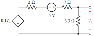
Q3. Referring to Fig. 3. (a) Determine the power absorbed by the 3.3 Ω resistor, (b) replace the 3.3 Ω resistor with another resistor such that it absorbs maximum power from the rest of the circuit.
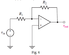
Q4. For the op amp circuit shown in Fig. 4 calculate vout if (a) R1 = R2 = 100 Ω and vin = 5 V and (b) R2 = 200R1 and vin = 1 V and (c) R1 = 4.7 kΩ, R2 = 47 kΩ and vin = 20sin5t V
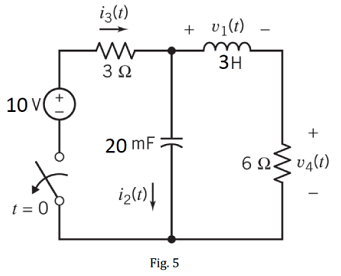
Q5. The circuit shown in Fig. 5 is at steady state when the switch opens at time t = 0. Determine v1(0-), v1(0+), i2(0-), i2(0+), i3(0-), i3(0+), v4(0-) and v4(0+).
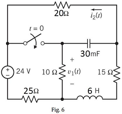
Q6. The circuit shown in Fig. 6 is at steady state when the switch closes at time t = 0. Determine v1(0-), v1(0+), i2(0-) and i2(0+).