JPEG
Many methods of lossy compression have been developed. On the other hand, a family of techniques called transform compression has proven the most valuable. The top example of transform compression is embodied in the popular JPEG standard of image encoding. JPEG is named after its origin, which is the Joint Photographers Experts Group. We will explain the operation of JPEG to demonstrate how lossy compression works.
We have already discussed a simple method of lossy data compression, coarser sampling and/or quantization (CS&Q in Table 27-1). This involves decreasing the number of bits per sample or entirely discards some of the samples. Both these events have the desired effect: the data file becomes smaller at the expense of signal quality. As you may expect, these easy methods do not work very well.
Transform compression is based on a straightforward premise: when the signal is moved through the Fourier (or other) transform, the out coming data values will no longer be equivalent in their information carrying roles. In the case , the low frequency components of a signal are more important than the high frequency components. Removing 50% of the bits from the high frequency components may remove, say, only five% of the encoded information.
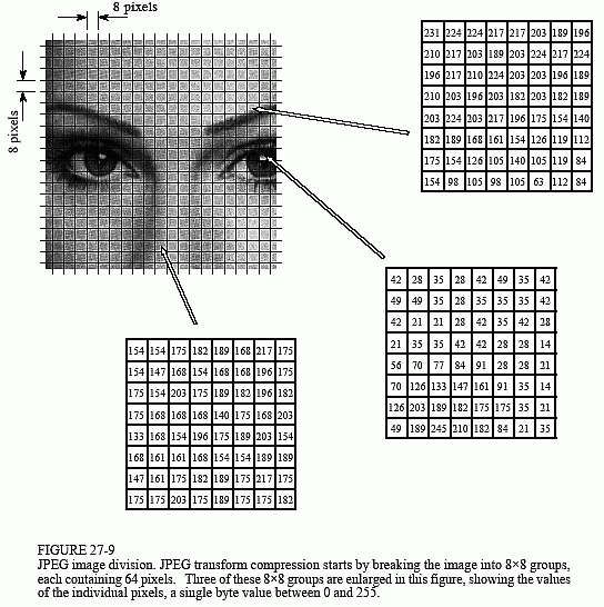
As shown in Fig. 27-9, JPEG compression starts by breaking the image into 8×8 pixel groups. The full JPEG algorithm could accept a wide range of bits per pixel with the use of color information. In this instance, every pixel is a single byte, a grayscale value between zero and two hundred fifty five. These 8×8 pixel groups are treated independently during compression. That is, every group is initially represented by sixty four bytes. After transforming and removing data, every group is represented by, say, two to twenty bytes. During uncompression, the inverse transform is taken of the two to twenty bytes to create an estimate of the original 8×8 group. These estimate groups are then fitted together to form the uncompressed image. Why use 8×8 pixel groups instead of, for instance, 16×16? The 8×8 grouping was based on the maximum size that integrated circuit technology could handle at the time the standard was developed. In whichever event, the 8×8 size works well, and it may or may not be changed in the future.
Many different transforms have been investigated for data compression, some of them invented purposely for this purpose. Like , the Karhunen-Loeve transform provides the best possible compression ratio, but is hard to implement. The Fourier transform is simple to use, but does not provide sufficient compression. After a lot competition, the winner is a member of the Fourier transform, the Discrete Cosine Transform (DCT).
Just as the Fourier transform uses sine and cosine waves to signify a signal, the DCT only uses cosine waves. There are more than a few versions of the DCT, with small differences in their mathematics. For an example of 1 version, imagine a one hundred twenty nine point signal that is running from sample zero to sample one hundred twenty eight. Now, make this a two hundred fifty six point signal by duplicating samples one through one hundred twenty seven and adding them as samples two hundred fifty five to one hundred thirty. specifically: 0, 1, 2, ..., 127, 128, 127, ..., 2, 1. We are here Taking the Fourier transform of this 256 point signal results in a frequency spectrum of one hundred twenty nine points, spread among 0 and 128. Because the time domain signal was forced to be symmetrical the spectrum's imaginary part will be composed of all 0s. In more words, we started with a one hundred twenty nine point time domain signal, and ended with a frequency spectrum of 129 points, each the amplitude of a cosine wave.
When the DCT is taken of an 8×8 group, it outcomes in an 8×8 spectrum. In other words, sixty four numbers are changed into sixty four other numbers. All these values are real and there is no complex mathematics here. Just as in Fourier analysis, every value in the spectrum is the amplitude of a basis function. Figure 27-10 shows six of the sixty four basis functions used in an 8×8 DCT, according to where the amplitude sits in the spectrum. The 8×8 DCT basis functions are given by:
The low frequencies exist in in the upper-left corner of the spectrum, whereas the high frequencies are in the lower-right. The DC part is at [0,0], the upper-left most value. The basis function for [0,1] is 1/2 cycle of a cosine wave in 1 direction, and a constant value in the other. The basis function for [1,0] is similar, just rotated by 90°.
The DCT computes the spectrum by correlating the 8×8 pixel group with every of the basis functions. That is, all spectral value is found by multiplying the suitable basis function by the 8×8 pixel group, and then adding the products. Two adjustments are then required to finish the DCT calculation.
JPEG is fine example of how a number of data compression schemes can be shared for better efficiency. The whole JPEG procedure is outlined in the following steps. 1st, the picture is broken into the 8×8 groups. 2nd, the DCT is taken of every group. 3rd, every 8×8 spectrum is compressed by the above methods: decreasing the number of bits and removing some of the components. This takes place in a single step and controlled by a quantization table.
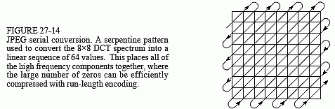
In the 4th step of JPEG encoding, the customized spectrum is converted from an 8×8 array into a linear sequence. The serpentine pattern uncovered in Fig. 27-14 is used for this step, inserting all of the high frequency components together at the end of the linear sequence. This Set the zeros from the eliminated components into long runs. The 5th step compresses these runs of zeros by run-length encoding. In the 6th step, the sequence is encoded by either Huffman or arithmetic encoding to form the final compressed file.
The amount of compression, and the resulting loss of image quality, could be selected when the JPEG compression program is run. Diag. 27-15 shows the type of image distortion resulting from high compression ratios. With the 45:1 compression ratio shown, every of the 8×8 groups is represented by only about twelve bits. Close inspection of this image shows that six of the lowest frequency basic functions are represented to some degree.
Email based Computer Science assignment help - homework help at Expertsmind
Are you searching Computer Science expert for help with JPEG questions? JPEG topic is not easier to learn without external help? We at www.expertsmind.com offer finest service of Computer Science assignment help and computer science homework help. Live tutors are available for 24x7 hours helping students in their JPEG related problems. We provide step by step JPEG question's answers with 100% plagiarism free content. We prepare quality content and notes for JPEG topic under computer science theory and study material. These are avail for subscribed users and they can get advantages anytime.
Why Expertsmind for assignment help
- Higher degree holder and experienced experts network
- Punctuality and responsibility of work
- Quality solution with 100% plagiarism free answers
- Time on Delivery
- Privacy of information and details
- Excellence in solving computer science questions in excels and word format.
- Best tutoring assistance 24x7 hours